
B
Brian HarrisAug 8, 2025
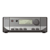
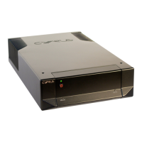
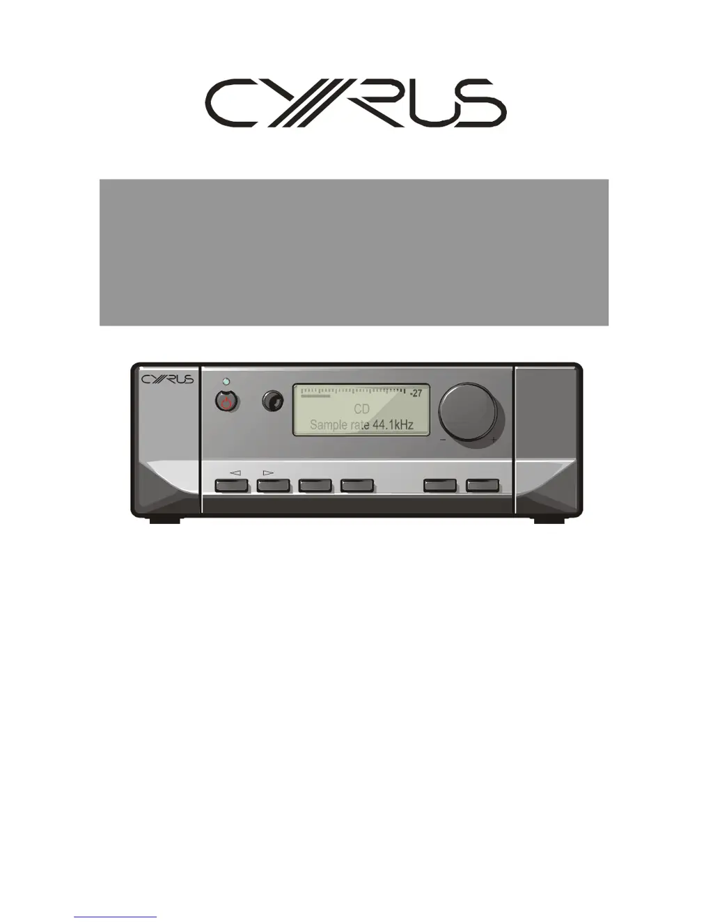
Why is there no sound from my Cyrus Media Converter?
- SSamuel MorenoAug 8, 2025
If there is no sound coming from your Cyrus Media Converter, here are several things to check: * Ensure the unit is not in Standby mode (the Standby light should be GREEN). * Make sure Mute is deselected. * Verify that the source is working correctly (e.g., the CD is playing, not paused). * Confirm the sample rate and sound format of the digital signal from the source are correct and within the amplifier's specifications, and that the program is encoded as two-channel stereo. * Check that the BAL control is not at an extreme limit and is centralized. * Inspect your speakers and replace any blown fuses. * Examine speaker cables and interconnects for faults; check connections and replace cables if needed.