TECHNICALDESCRIPTION
©CyrusAudioLtdJun2014 10 Cyrus6DAC,Cyrus8DACservicemanualIssue1
Theprotectioncircuits
Over‐current protection is achieved by detecting the voltage across the dual emitter resistor
R219. When a high level of current isdetected T304will turn on,switching T307on etc. The
outputsignalfromthisdetectoristhensenttothemicrocontroller.
If the DC conditions of the amplifier drift beyond acceptable limits, thisis detected by IC200
andassociatedcircuitryandprotectionwillbeactivated.
Thermal protection is achieved by the microcontroller detecting a high temperature reading
fromthethermalsensor.
Power supply failure is detected by IC402 arranged as a window comparator. The window
range is set between 19V and 60V, as the amplifier will workbetween these voltages. If the
supply voltage is outside that range a power supply error signal is sent to the control
microprocessor.
Mainsdisconnectionisdetectedbythecontrolmicroprocessortopreventswitchoffnoise.
Thecontrolsystem
The system microcontrollerand the displayare housed ona PCB attachedtothe back ofthe
front panel assembly. The inputs to the microcontroller read when the keys are pressed, a
remote control or MC‐BUS command is received and also monitor the working status of the
amplifierviafaultdetectionlines.Themicrocontrolleristhenconfiguredtoupdatethedisplay
andsetthevolume,inputandothersectionswithintheamplifier.
The front panelcontrolsystem PCB is connectedtothemainPCB via asingle25way flexible
cable.Asecond13wayflexiblecableconnectsdirectlyfromthefrontpanelPCBtothedigital
PCB. Note that this flexible cable is inverted compared to the 25 way cable. When correctly
installed,thewritingwillbevisibleonthe13waycable,andnotvisibleonthe25waycable.
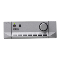
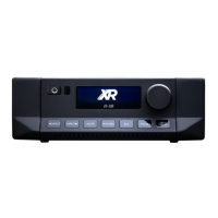
ThefrontpanelcontrolPCBchangedduringthecourseofmanufacturingtheseamplifiers.The
second‐generation PCB includes a push function on the rotary encoder, whereas the first‐
generationPCBdoesnot.Moreinformationaboutthedifferencesbetweenthetwoversionsis
shownonthenextpage.