I
0
INPU T A
STERE O
PARALLE L
BRIDG E
C&D
A&B
Output:A
Output:A
1+:HOT
1- :COLD
Output:B
Output:B
1+:HOT
1- :COLD
Output:A
1+:HOT
2- :COLD
[BRIDGE]
Input:A,
Output:C
1+:HOT
1- :COLD
Output:D
1+:HOT
1- :COLD
Output:C Output:D
INPU T B
INPU T C
INPU T D
Output:C
1+:HOT
2- :COLD
[BRIDGE]
Input:C,
2
Ω
2
Ω
0.775V 0V 32dB
100VAC-240VAC
50Hz-60Hz
PUSH
PUSH
PUSH
PUSH
Input sensivity choice;
The input sensivity choice of this device is
0.775V( factory seng ),1V,32dB
0.775V
1V
32dB
Input mode choice
Stereo mode( factory mode)
When set as the figure, channels A and B are in stereo mode, set
each channel volume directly. Operaon of Channels C and D
will be the same;
Parallel mode
When set as the figure, channels A and B are in parallel mode, input
signal into channel A , then both, A and B channels use the same signal
Set each channel volume directly. Operaon of
Channels C and Channel D will be the same.
Bridge mode
When set as the figure, channels A and B are in bridge mode, input
signal into channel A, channels A and B will operate as a mono
output, volume control of Channel A will manage both channels. Operaon of
Channels C and Channel D will be the same.
STEREO
PARALLEL
BRIDGE
STEREO
PARALLEL
BRIDGE
STEREO
PARALLEL
BRIDGE
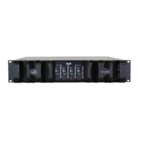
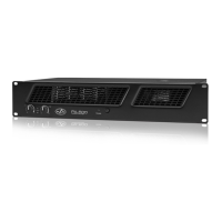
FRONT PANEL
A) Level control
Four level potentiometers are located at the front panel
providing individual channel attenuation. Level range
varies from - 50dB to 0dB. The 12 o´clock position equals
to -25dB attenuation
B) Power ON Indicator
This LED lights when the mains switch is pressed. If it does
not light up, the unit is not connected to the mains or the
mains fuse has blown.
C) Signal indicator
This LED lights up if signal is detected at the amplier´s
output channel. The indicator goes off when no signal or
when a protective circuit has been activated in the
amplifier.
D) Limit
This LED lights up if the limiter threshold has been
reached and the amplifier is being operated at the clip
level. When the LED flashes permanently the volume of
the input audio source should be reduced or the gain
control of the amplif ier´s channel turned counter
clockwise.
E) Power Switch
The unit is switched on by the use of the power switch.
Loudspeaker outputs are switched on via delayed relays in
order to avoid audible transients.
A
BC
E
D
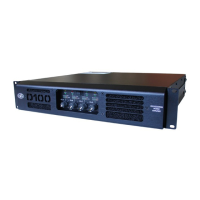
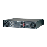
REAR PANEL
9
EP series / User’s Manual
 Loading...