Do you have a question about the D.A.S. D-100 and is the answer not in the manual?
Covers warnings related to electrical connections, earthing, and secure rack mounting for user safety.
Details precautions against moisture, heat, proper ventilation, and safe handling of power cords.
Explains the symbol for not treating the product as household waste and proper recycling.
Details electrical safety requirements for installing the apparatus, including earthing and mains connections.
Outlines mechanical installation procedures, focusing on secure rack mounting and ventilation to prevent overheating.
Explains the 'dynamic amplifier' concept, high peak power, and automatic signal reduction for protection.
Provides guidance on operating procedures, including initial power-up indications and troubleshooting.
Instructions for qualified personnel on cleaning filters, vents, and casework, plus servicing advice.
Describes the function of the power switch and power status indicator LED.
Explains attenuation controls and the Auto Protect (A/P) LED, which indicates protection circuit activation.
Details Signal LEDs, Limit LEDs indicating limiter operation, and the Link LED for channel pairing.
Explains the PRC LED, which illuminates when the Power Reduction Control is enabled on a channel.
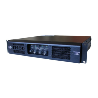
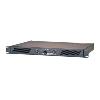
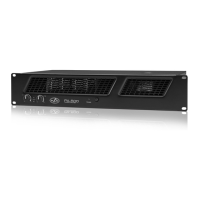
Details the XLR input sockets and Speakon output connectors for D-10, D-20, and D-100 models.
Explains the switch used to configure the amplifier for bridged (mono) operation.
Describes the function of link out sockets for parallel input connections to other amplifiers.
Explains how PRC switches limit amplifier power output in three stages.
Details XLR input wiring for balanced signals and Speakon output wiring for speaker connections.
Guides on setting up bridged mode using centre Speakon connectors and minimum impedance requirements.
Details specific output connector pin assignments for bi-amping and bridged operation on D-100.
Explains how to adjust internal gain settings (26, 32, 36dB) for D-100 and D-20 models.
Provides tables detailing current draw and thermal emissions under various load and signal conditions.
Shows maximum output power levels for different PRC settings into 8, 4, and 2 ohm loads.
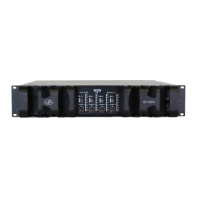
Details the T Line chassis, its transformer configurations, and technical specifications like power handling.
Explains the SPEAKON connector pinouts for T Line inputs/outputs and rack mounting considerations.
Explains the necessity of low frequency roll-off to prevent transformer saturation and how to adjust it.
Details the primary and secondary wiring for 500W single 100V winding transformers.
| S/N Ratio | > 100 dB |
|---|---|
| Weight | 15 kg (33 lb) |
| Frequency Response | 20 Hz - 20 kHz, +/-0.5 dB |
| THD | < 0.05% (20 Hz - 20 kHz) |
| Input Sensitivity | 1V |
| Total Harmonic Distortion | < 0.05% (20 Hz - 20 kHz) |
| Dimensions | 88mm x 483mm x 300mm |