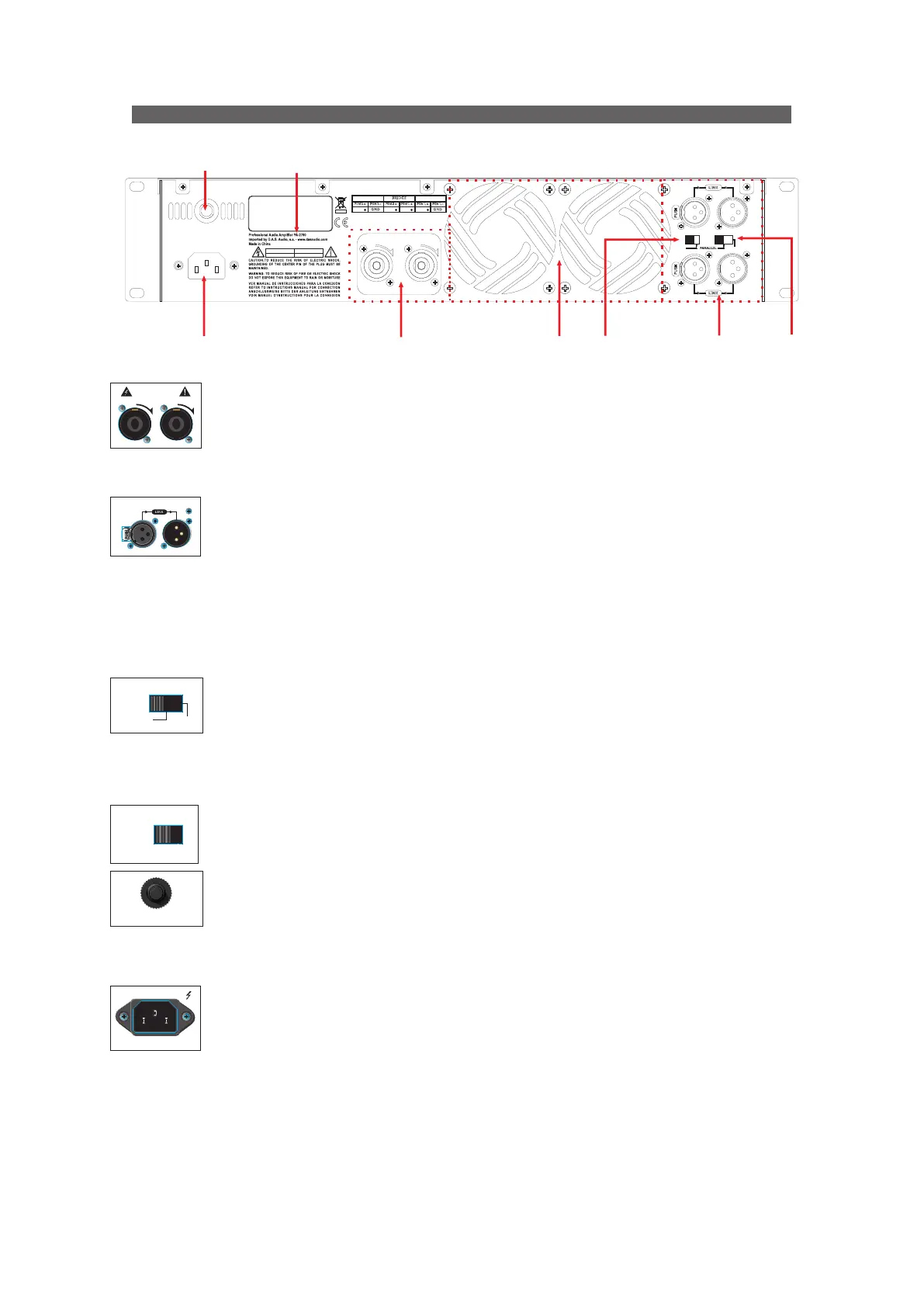
Mode switch (C)
STEREO mode makes the two channels work independently, CH1 input signal by CH1
output, CH 2 input by CH2 output.
BRIDGE mode makes CH1 input signals from the BRIDGE output socket, output
must use CH1 volume control to adjust the volume.
PARALLEL mode makes CH1 input signal by CH1 and CH2 output socket output.
The input socket of Ch2 has no effect. Channel's volume can be adjusted independently.
Speaker outputs (A)
Connecting speakers to each output it is done through Speakon-type connectors whose
pin assignments are:
Channel 1 (stereo and parallel modes) : pin +1 = positive / pin -1 = negative
Channel 2 (stereo and parallel modes) : pin +1 = positive / pin -1 = negative
Channel 1 (bridge mode) : pin +1 = positive / pin +2 = negative
Inputs (B)
CH1 and CH2 are directly connected to the mixer, the input and output connectors
of the respective channel are put together, to provide fixed connection, and no need to
consider the power switch setting.
The nominal input impedance of 20kohms and 10kohms balanced mode in non-balanced
mode.
The pin assignment is according to the standard AES14-1992 (ANSI S4.48-1992):
Pin 1 (XLR) : GND (Ground)
Pin 2 (XLR) : (+) Non-inverted signal
Pin 3 (XLR) : (-) Inverted signal
Sensitivity mode (D)
This switch allows to set the sensitivity between 0.775V or 1.4V.
Cooling air outlet grilles (G)
Fan cooling permits airflow through the most vital parts of the amplifier. Since the airflow
finds its way out through these grilles, keep them as clean and dust-free as possible to assure
proper cooling.
Circuit breaker (E):
When amplifier is overloaded (caused by the small load impedance of the amplifier or the
continuous input signal), the button of the circuit breaker will upspring immediately, and will be
cutoff power automatically to protect the amplifier. You must exclude overload condition, and
then press the button of the circuit breaker, and the power amplifier will resume to normal
operation.
Power outlet (F)
The amplifier is provided with a socket IEC320-C14. When using the amplifier, one
should check whether the selected voltage is correct or not. If the voltage is wrong,
it could damage the amplifier. Please ensure that the device is connected to the
power supply with ground to use.
BACK PANEL DESCRIPTION
6
CH 2
CH 1CH 1
CH 1
CH 2 CH 2
23 0V~50 /60Hz 1 50W
RES ET
SE NSI TI VIT Y
MO DE
1.4 V
0.7 75V
BR IDG E
ST ERE O
INP UT
CH2
INP UT
C H 1
CAU TION ATTEN TION
RISK OF ELECTRIC SHOCK
DO NOT OPEN
DANGER D’ELECTROCUTION
NE PAS OUVRIR
CH 2 CH 1
LO CK
OUT PUT
LO CK
BR IDG E
22 0V ~50/6 0H z
INP UT C H 1
OU T P U T
CH 2 CH 1
LO CK LO CK
MO D E
BRID G E
PA RAL L E L
STE R E O
SE N S ITI V I T Y
1. 4V
0. 775V
RESET
F
E
D
B
A
Model
G
C
Manual de Usuario de Amplificadores / PA series / User’s Amplifier Manual
 Loading...