3
Restart Your Computer
Connecting Additional Computers
To The DI-524
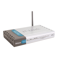
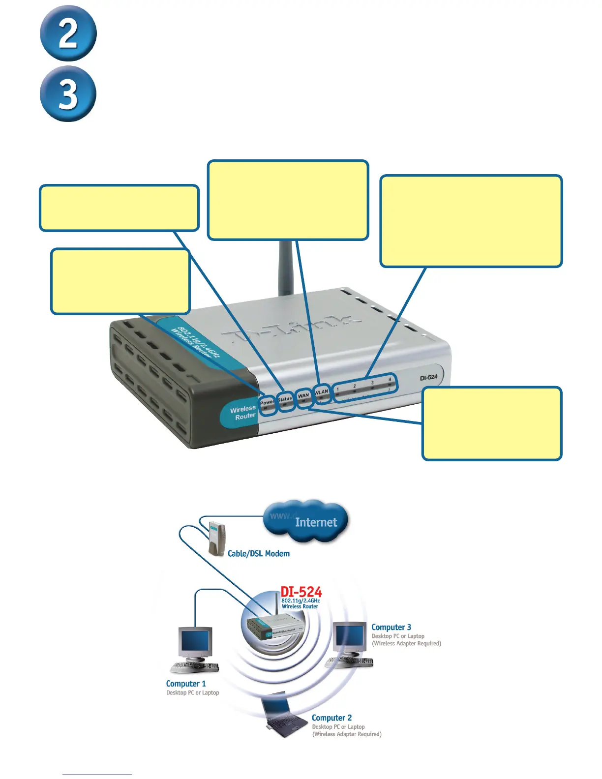
LOCAL NETWORK LEDs – a
solid light on the port indicates
a connection to an Ethernet
enabled computer on ports 1-4.
This LED blinks during data
transmission.
Power LED – a solid
light indicates a proper
connection to the power
supply.
Status LED – a blinking light
indicates that the DI-524 is
functioning properly.
When you have completed the steps in this Quick Installation Guide, your connected
network should look similar to this:
Using additional Ethernet (CAT5 UTP) cables, connect your Ethernet-equipped
computers to the remaining Ethernet LAN ports on the back panel of the DI-524.
WAN LED – a solid light
indicates connection
on the WAN port. This
LED blinks during data
transmission.
WLAN LED – a solid light
indicates that the wireless
segment is ready. This LED
blinks during wireless data
transmission.
 Loading...