Do you have a question about the D-Link DMC-700SC and is the answer not in the manual?
Defines Link Loss Carry Forward (LLCF) behavior when TP or fiber links fail, signaling errors.
Defines Link Loss Return (LLR) behavior when fiber links fail, disconnecting transmit.
Configures fiber mode between Forced and Auto-Negotiation for optimal link compatibility.
Enables or disables the Link Loss Return (LLR) function to manage link loss signaling.
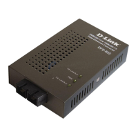
| Type | Media Converter |
|---|---|
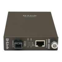
| Model | DMC-700SC |
| Ports | 1 x 10/100Base-TX, 1 x 100Base-FX |
| Connector Type | RJ-45, SC |
| Data Transfer Rate | 100 Mbps |
| Power Supply | External Power Adapter |
| Humidity | 5% to 90% non-condensing |
| Standards | IEEE 802.3, IEEE 802.3u |
| Fiber Type | Multi-mode |
| Wavelength | 1310nm |
| Maximum Fiber Distance | 2 km (Multi-Mode) |
| Operating Temperature | 0 to 40 °C (32 to 104 °F) |
| Storage Temperature | -20°C to 70°C |