4.1 Overview
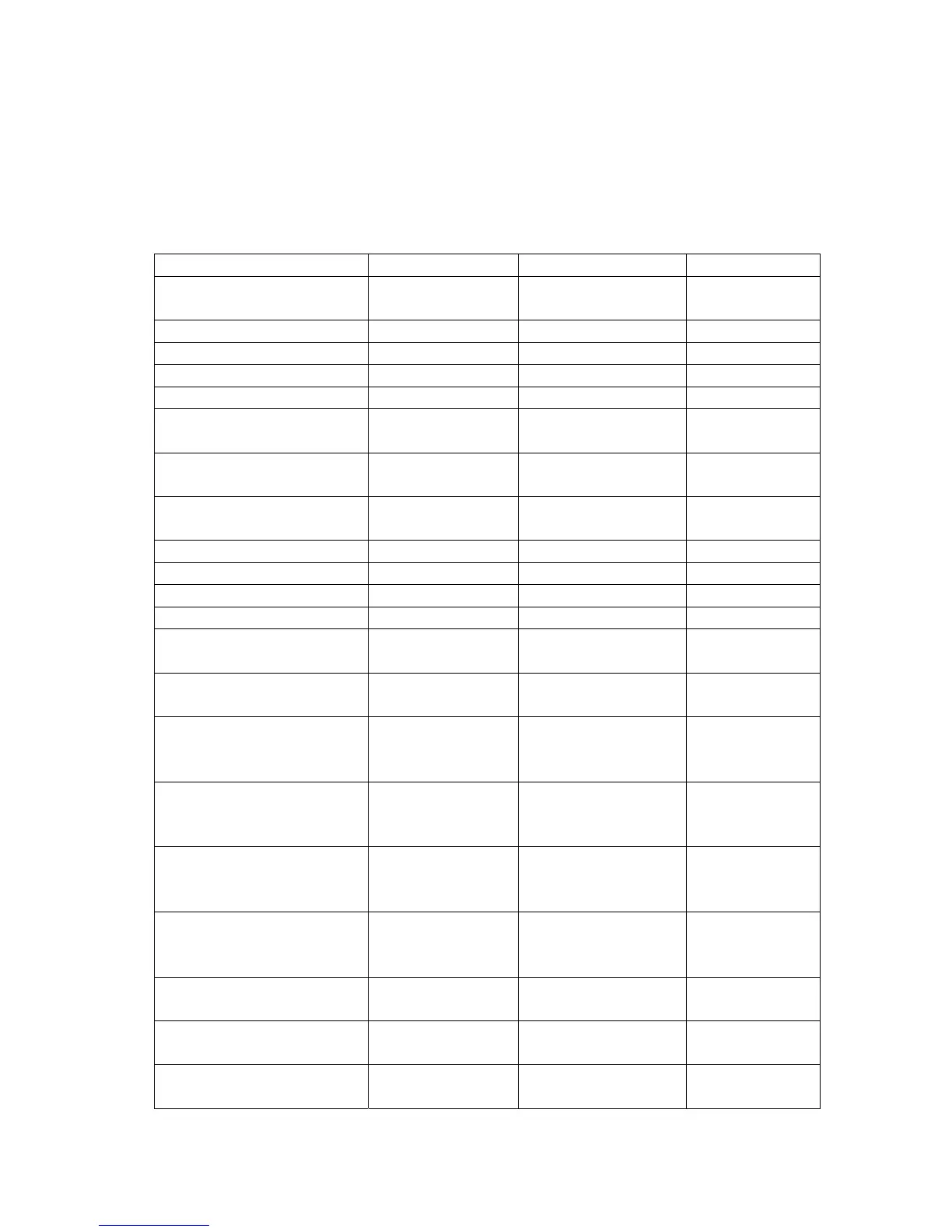
The following tables show a summary of the interfaces on the devices you configure,
along with their IP address and port information as well as the VLANs, DHCP pools, etc.
This configuration starts from scratch and therefore you should clear the configuration on
the WLAN switches from the previous scenarios.
Interface/Device VLAN ID/Name IP Address Port
WS1 Management
Interface
NA 10.90.90.90/8 Any unused L2
port
WS1 Loopback Interface NA 192.168.10.250/32 Logical only
WS1 L3 Tunnel Interface 2 - RD 192.168.2.254/24 Logical only
WS1 L3 Tunnel Interface 3 - Sales 192.168.3.254/24 Logical only
WS1 L3 Tunnel Interface 100 - Guest 192.168.100.254/24 Logical only
WS1 Interface to L3
Device
10 - Core 172.17.5.253/24 0/24
L3 Device Interface to
WS1
NA 172.17.5.254/24 L3 device port
WS2 Management
Interface
NA 10.90.90.91/24 Any unused
WS2 Loopback Interface NA 192.168.20.250/32 Logical only
WS2 L3 Tunnel Interface 2 - RD 192.168.2.253/24 Logical only
WS2 L3 Tunnel Interface 3 - Sales 192.168.3.253/24 Logical only
WS2 L3 Tunnel Interface 100 - Guest 192.168.100.253/24 Logical only
WS2 Interface to L3
Device
10 - Core 172.17.6.253/24 0/24
L3 Device Interface to
WS2
NA 172.17.6.254/24 L3 device port
FTP or other Server on
WS1
5 - Server 192.168.5.254/24
192.168.5.x/24 for
server
0/13
RADIUS Server on WS2 4 - Server 192.168.4.254/24
192.168.4.x/24 for
server
0/13
AP1 on WS1 101 – AP1 192.168.101.254/24
192.168.101.x/24
for AP
0/1
AP2 on WS2 102 – AP2 192.168.102.254/24
192.168.102.x/24
for AP
0/1
DHCP for Clients on
Guest SSID
NA 192.168.100.x/24 Wireless
DHCP for Clients on D-
LINK-NET1 SSID
NA 192.168.2.x/24 Wireless
DHCP Clients on D-
LINK-NET2 SSID
NA 192.168.3.x/24 Wireless
 Loading...