14
SETTING THE OPEN & CLOSE LIMITS ....Menu 1
1) Ensure the baery is connected to the operator.
2) Press the SET buon to enter the Programming Menu (Pr).
3) Press the DOWN buon unl Li is visible.
4) Press the SET buon. The display will change to oL.
5) Use the UP and Down buons to move the door to the OPEN posion. The Trolley
must stop 2mm away from the Sprocket Assembly. If the Trolley does not reach the
Sprocket Assembly, then a Channel End Stopper (not supplied) must be fied
I
6) When the door is in the open posion, press the SET buon. The display will change
to cL.
7) Use the UP and Down buons to move the door to the CLOSE posion.
8) When the door is in the closed posion, press the SET buon. The display will change
to CL. Adjust the Lower Limit Adjusng Bolt to be 2mm above the floor.
9) The open and closed limits are now set.
SET
P r
SET
o L
l i
SET
c L
SET
C L
1) Ensure the baery is connected to the operator.
2) Press the SET buon to enter the Programming Menu (Pr).
3) Press the DOWN buon unl the Force Limit Menu (Fo) is visible.
4) Press the SET buon to enter the Force Limit Menu. The display will change to the
current Force Limit value F3 (this is the default seng).
5) Press the UP and DOWN buons to scroll through the Force Limit values. F0
(minimum force) to F9 (maximum force). ***
6) Press the SET buon on the chosen Force Limit value to accept.
*** Cauon: too high a force seng could cause injury or damage!!
SET
F o
SET
p r
SET
F 3
1) Ensure the baery is connected to the operator.
2) Press the SET buon to enter the Programming Menu (Pr).
3) Press the DOWN buon unl the Beams Menu (bE) is visible.
4) Press the SET buon to enter the Beams Menu. The display will change to (by)
5) Press the UP and DOWN buons to toggle between ENABLE (by) and DISABLE (bn).
6) Press the SET buon on either ENABLE (by) or DISABLE (bn) to select.
b E
SET
SET
p r
SET
b y
SETTING THE OPENING & CLOSING FORCE ....Menu 2
ENABLE OR DISABLE SAFETY BEAMS ....Menu 3
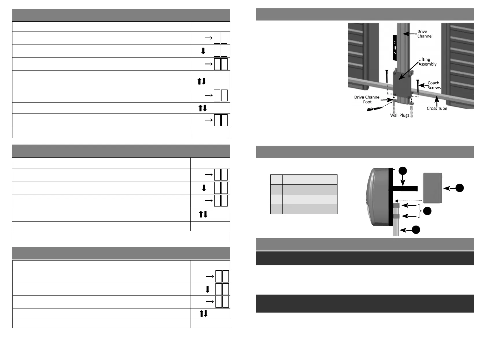
SECURING THE DRIVE CHANNEL FOOT TO THE FLOOR
POSITIONING & SECURING THE BATTERY
Place the 12 volt baery on top of the Drive Channel at the back of the operator and secure it in place with the
Velcro straps that are in place.
Please Note:
Before applying power to the operator, manually li the door/s to ensure that there is free movement of the
Liing Assembly on the Drive Channel.
Li the door/s manually to various heights and ensure that the door/s do not close under their own weight. If
they do then it will be necessary to get an experienced door fing contractor to tension the door springs.
1 Velcro straps
2 12v Baery
3 Door U-Brackets
4 Drive Channel
11
1) With the door/s sll closed, and ensuring
that the Manual Release Mechanism has
been released, li the door/s by hand,
holding the Cross Tube. The door/s need
only be lied about 50cm and then lowered
again to the closed posion. This procedure
will automacally place the Drive Channel
Foot the correct distance from the wall.
2) Without moving the Drive Channel toward
or away from the door, use a Spirit Level to
confirm that the channel is sll vercal.
3) Make marks on the floor through the two
holes in the Drive Channel Foot.
4) Move the Drive Channel slightly, enough to
allow for holes to be drilled in the floor and
the 10mm wall plugs to be inserted.
(The Door Liing Tube/s can be removed to
make this easier).
5) Move the Drive Channel back into posion
and fasten the Drive Channel Foot to the
floor using the two coach screws
BEFORE PROGRAMMING & COMMISSIONING THE OPERATOR
The LUX DC12 operator uses the 12V baery for normal operaon, it is important that the baery is always
connected when the operator is in use.
▶
Seng the Open and Close limits:
Aer the operator has been assembled, fastened to the wall and aached to the door (s), it must be
programmed to recognise the door’s Open and Close limits.
On first power up, or aer a factory reset, the operator’s LED display will flash nL. This is the indicaon that the
door limits need to be set. The operator will not allow operaon of the door unl this process has been
completed.
Follow ‘Seng the Open and Closed Limits...Menu 1’ to program the limits for the door(s).
Once the limits have been set, the door can be opened and closed using the UP or DOWN buons on the
operator.
If, aer the inial setup, the limits need adjusng the Programming Menu (Pr) can be entered again by pressing
the SET buon and the limits can be reset. Refer to ‘Seng the Physical End Stops’ on page 13.
Note: Depending on the motor wiring polarity, the UP and DOWN buons on the operator may not
necessarily correspond with the actual direcon that the door is moving in. The operator will automacally
correct this once the Open and Close Limits have been set.
4
3
2
1
 Loading...