GLOSSARY
An-Crush Gap
This is the small secon of travel near the end of the door’s closing cycle. If the operator
receives a trigger in this secon of travel, the door will reopen to prevent possible damage
or injury.
Auto Close
Funcon
When set, this funcon will enable automac closing of the garage door aer a set period
of me.
Balanced Door
When the force required to open the garage door is equal to the force required to close
the garage door.
Control Board
The main electronic circuit board housed inside the operator.
Courtesy Light
The light, built into the operator Control Card, which switches on during each door operaon
and can also be operated by pressing a programmed buon on a remote control.
Door Balance
The even distribuon of the doors opening and closing forces.
Drive Channel
The steel channel housing the Chain, Liing Assembly and Manual Release Mechanism
Fuse
A removable electronic component on the Control Card that protects the Control Card
from damage in the case of severe forces being applied.
Infrared Safety
Beams
Oponal electronic sensors which prevent the garage door from closing if the infrared
beam, being transmied between the sensors, is blocked, indicang an obstrucon.
LED Display
Electronic alphanumeric display on the operator used to assist with programming and
fault finding.
Lockout
An electronic security feature that will prevent the door from receiving a trigger while the
funcon is acve.
Manual Release
Mechanism
The lever assembly that is used to place the garage operator into manual mode, allowing
for the garage door to be operated manually.
Obstacle
Sensing
The detecon of an obstacle causing the moon of the door to be impeded through the
processing of algorithms in the garage door operator’s soware.
Onboard
Receiver
An integrated part of the Control Card which receives the signal from the Remote Control
to trigger of the operator.
Ramp Down
Process of the operator slowing down the door’s travel speed towards the end of the
door’s travel.
Remote Control
The hand held device used to acvate the opening and closing of the operator.
Remote Buon
One of several buons on a remote control used to acvate various funcons.
Solar Panel
An oponal device connected directly to the Control Card to make use of sun energy
instead of a buildings mains supply for charging the operator's baery.
Transformer
An external device connected to the buildings mains supply via a plug point that reduces
the mains voltage to a safe voltage to charge the operators baery.
4
21
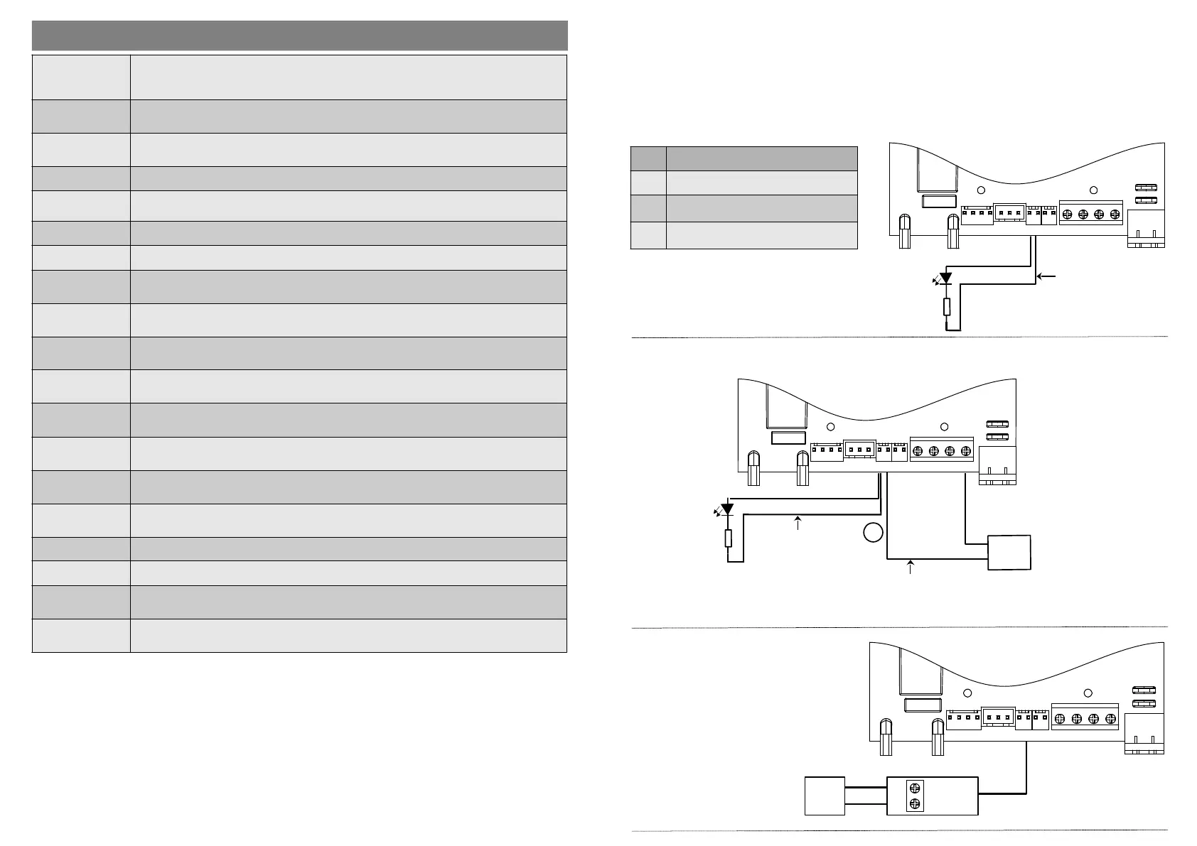
4. Status Output (auxiliary)
The Status output is used to provide feedback from the operator on the current posion of the Trolley on the
Drive Channel and the mains supply status. Most commonly used for the Status Output is an LED, connected to
the operator. The LED can be placed in a convenient locaon for ease of use.
It is important to understand that the Status Output only indicates the operaonal status of the operator and
not the door. To explain, imagine the door is closed and the LED indicates that the operator is closed. The door
is then placed in manual mode and opened manually, however the Trolley has not moved and remains in the
closed posion, the LED will connue to indicate that the status of the operator as closed. When the door is
reconnected to the Liing Bracket (placed back in automac mode), the status of both the door and operator
will be closed. Refer to ‘Seng Auxiliary Output....Menu 5’ for programming.
LUX DC12
Control Board
2K7
Resistor
LED
+ve
-ve
Open Collector
Harness
(Double Wire)
Code: SA004
Resistor & LED not included.
5. Low Baery Output (auxiliary)
This output will provide indicaon when the baery is low. An LED or a GSM transmier can be used.
Refer to ‘Seng Auxiliary Output....Menu 5’ for programming.
LUX DC12
Control Board
2K7
Resistor
LED
+ve
-ve
Open Collector
Harness
(Double Wire)
Code: SA004
Resistor & LED not included.
GSM Module
INPUT
COM
Open Wire
Connector
(Single Wire)
Code: SA044
OR
LED OPERATOR & MAINS STATUS
ON The operator/door is open
OFF
The operator/door is closed and the
mains is off.
BLINK
The operator/door is closed and the
mains is on.
REVLIMITS AUX LOCK 12V TRIG INF GND
Power
Input
REVLIMITS AUX LOCK 12V TRIG INF GND
Power
Input
6. Trigger Output (auxiliary)
The Trigger Output is used to
trigger other external devices at
the same me that the door
operator is triggered. These
devices can include buzzers
inside the house which sound
when the garage door is
triggered. Another example is
the switching on of lights or the
deacvaon of the home alarm
by triggering a Pulse Stretcher.
Refer to ‘Seng Auxiliary
Output....Menu 5’ for
programming.
NO
COM
DACE
Relay Module
Code: SA001
TRIGGER
GND
External
Trigger
LUX DC12
Control Board
REVLIMITS AUX LOCK 12V TRIG INF GND
Power
Input
 Loading...