20
2. Safety Beams
Safety Beams are used for the early detecon of an object obstrucng the closing door that could result in
damage or injury. While Safety Beams will detect most obstrucons including cars, people and pets, it may not
necessarily detect all obstacles but will greatly reduce the risk. It is highly recommended that Safety Beams are
fied when automang a garage door.
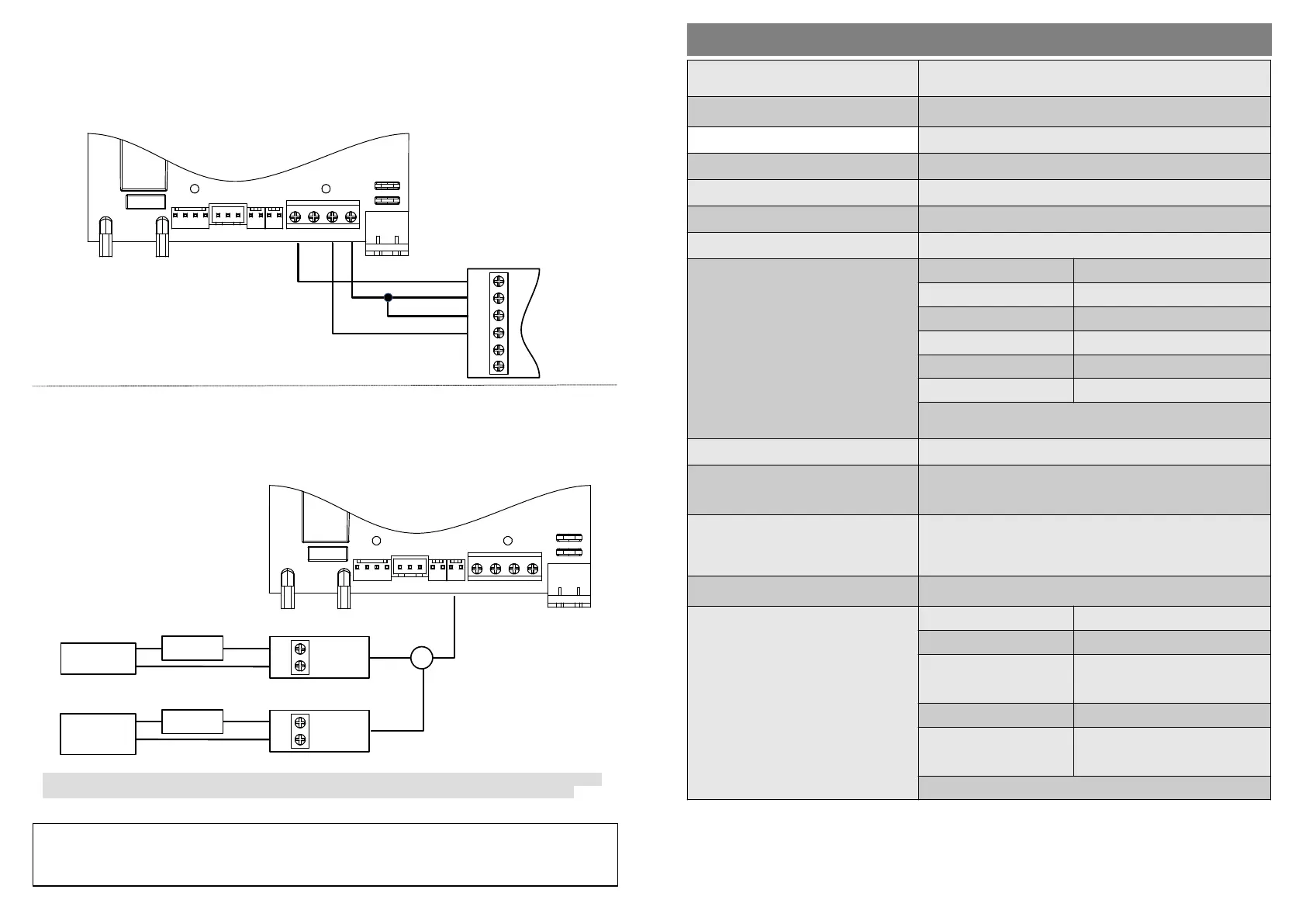
For the purposes of the wiring diagram DuraOpcs Wireless Safety Beams (code DOPT03) are shown.
Refer to ‘Enable or Disable Safety Beams....Menu 3’ for programming.
3. Electric and Magnec Locks
An automated door must not be locked using a padlock as both the door and the operator could be damaged
should the operator be triggered while the door is locked.
If extra security is required the door can be locked using either an Electric Lock (strike lock) or a Magnec Lock
(power lock) and controlled by the operator.
Refer to ‘Enable or Disable Electric/Magnec Lock....Menu 6’ for programming.
LUX DC12
Control Board
OR
NO
COM
DACE
Relay Module
Code: SA001
NO
COM
DACE
Relay Module
Code: SA001
Electric Lock
Magnec Lock
External
Power
Supply
+ve
-ve
Operator
Baery
+ve
-ve
Aer connecng the lock, it is important to select the correct lock type in the operator’s Programming Menu,
as selecng the wrong lock type may cause damage to the lock or cause the lock to funcon incorrectly.
PL - Magnec / Power Lock
EL - Electric / Strike Lock
REVLIMITS AUX LOCK 12V TRIG INF GND
Power
Input
LUX DC12
Control Board
DuraOpcs Wireless
Safety Beams
REVLIMITS AUX LOCK 12V TRIG INF GND
NO
GND
COM
12V/
24V
NC
FET
Power
Input
Cauon:
When fing a Magnec Lock to the door, no NOT use the power from the operator as the lock will drain the
operator’s baery power.
Only use an external source to power the Magnec Lock.
Transformer Input Voltage
220 - 240V AC @50Hz
Output Voltage: 16VAC
Board Input Supply 12 - 18V AC or 17 - 22V DC
Motor Voltage 12V
Motor Power (Rated) 150W
Maximum Holding Capacity 1200N
Maximum Push/Pull Force 50kgF
Baery 12V DC
Maximum Daily Operaons
(or in standby *)
* Operaons in standby is dependent on
charge level of baery and duraon of
power loss.
The number of operaons is calculated
using a 12V 5Ah baery. Using a bigger
Ah rated baery will increase the
operaons in standby and standby
duraon but will not allow for more daily
operaons.
Push/Pull Force Operaons (Cycles)
10kgF 110 (55)
20kgF 86 (43)
30kgF 62 (31)
40kgF 40 (20)
50kgF 16 (8)
Operaons: either Open or Close
Cycles: both Open and Close
Maximum Door Size 15m
2
Travel Speed
Note: Travel speed is dependent on load
and baery voltage.
8.5m/min
Outputs
Auxiliary: Adjustable to be either a light, trigger, status or low
baery indicator.
Lock: Adjustable to funcon with either an electric or
magnec lock.
Inputs External Trigger and Beams
Features
Programmable Limits Adjustable Force Sengs
Infrared Beam Input Lock Output
Auxiliary Output: Light,
Trigger, Door Status or
Baery Status
Trigger Input
Holiday Lockout Single Remote Erase
Up to 64 Programmable
Remotes
Remote Buons can be set to
acvate the light or lockout
funcons individually
Adjustable Auto Close Funcon
TECHNICAL SPECIFICATIONS
5
 Loading...