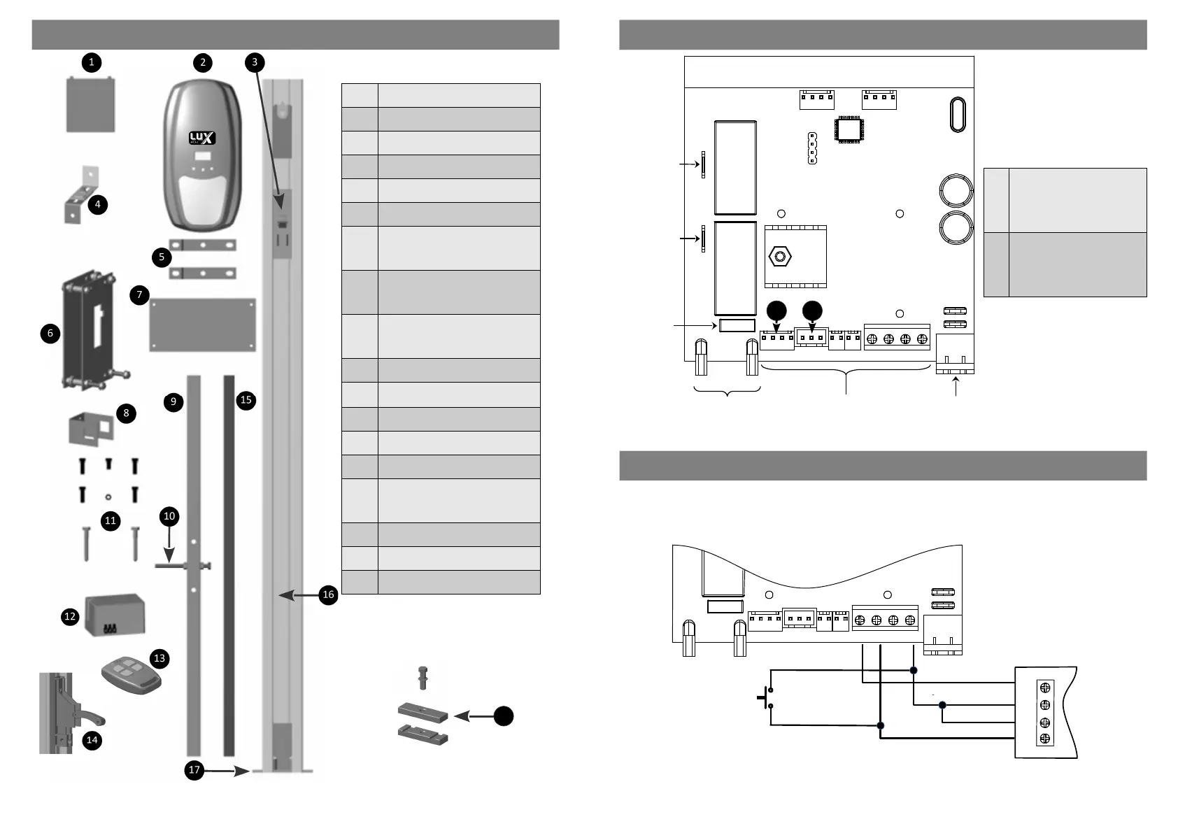
PARTS IDENTIFICATION
6
1 12v Baery
2 Power Head
3 Trolley
4 Floang Bracket
5 Power Head U-Brackets
6 Liing Assembly
7
Door Reinforcing Plate:
Single Door - (x2)
Double Door - (x4)
8
Door U-Bracket:
Single Door - (x2)
Double Door - (x4)
9
Cross Tube:
Single Door – 600mm
Double Door - 1000mm
10 Lower Limit Adjusng Bolt
11 Fasteners
12 Transformer
13 4 Buon Remote (x2)
14 Manual Release Mechanism
15
Door Liing Tube
Single Door - (x1)
Double Door - (x2)
16 Drive Channel
17 Drive Channel Foot
18 Channel End Stopper (oponal)
Oponal part.
Not supplied in kit.
18
CONTROL BOARD LAYOUTCONTROL BOARD LAYOUT
REVLIMITS AUX LOCK 12V TRIG INF GND
Inputs / Outputs Power Input
12 – 18V AC
or
17 – 22V DC (Solar)
+ve -ve
Baery Cables
Motor Wire
(Red)
Motor Wire
(Black/Blue)
20A Fuse
(Motor)
DBUS
Input
Marker
Input
19
1
LIMITS:
Connect the 4 pin plug from
the Drum Mount Operator
(this is not used on Seconal or
Vercal Mount Operators).
2
REV:
Connect the 3 pin plug from
the motor to the connector.
(this is not used on Drum
Mount Operators).
1 2
ADVANCED CONTROLLER PROGRAMMING OPTIONS
1. External trigger:
The LUX operator can be acvated using other external devices such as Push Buons, external Receivers or GSM
Receivers.
LUX DC12
Control Board
External Receiver
REVLIMITS AUX LOCK 12V TRIG INF GND
NO
GND
COM
12V/
24V
External
Push Buon
Power
Input
 Loading...