ERASING ALL REMOTES and THEIR BUTTONS FROM THE OPERATOR
1) Ensure the baery is connected to the Operator.
2) Press the SET buon to enter the Programming Menu (Pr).
3) Press the DOWN buon unl the Remote Menu (rc) is visible.
4) Press the SET buon to enter the Remote Menu. The display will change to LE
(Learn).
5) Press the DOWN buon unl Er is visible.
6) Press the SET buon. While holding the SET buon, press either the UP or DOWN
buon. Connue to hold the two buons unl the visible countdown on the LED
display is complete (E5 to E0). All remotes have now been erased from the operator.
7) Exit the Programming Menu by scrolling to bc and pressing the SET buon.
R c
SET
p r
SET
b c
SET
L E
E r
PROGRAMMING A REMOTE BUTTON TO SET THE HOLIDAY LOCKOUT FEATURE
1) Ensure the baery is connected to the Operator.
2) Press the SET buon to acvate the Programming Menu (Pr).
3) Press the DOWN buon unl the Remote Menu (rc) is visible.
4) Press the SET buon to enter the Remote Menu. The display will change to LE
(Learn).
5) Press the DOWN buon unl Lo is visible.
6) Press and hold the remote buon that will be used to acvate the Holiday Lockout
feature.
7) While holding the remote buon, press the SET buon on the operator. The display
will indicate the stored posion of the remote being programmed (01 to 64). The
buon has now been programmed.
8) To exit the Holiday Lockout Menu (Lo), use the UP or DOWN buons to scroll to bc
and press the SET buon. This will return you to the Programming Menu (Pr).
R c
SET
p r
SET
b c
SET
L E
18
L o
SET
1) Ensure the baery is connected to the Operator.
2) Press the SET buon to enter the Programming Menu (Pr).
3) Press the DOWN buon unl the Factory Reset (Fr) is visible.
4) Press the SET buon. While holding the SET buon, press either the UP or DOWN
buon. Connue to hold the two buons unl the visible countdown on the LED
display is complete (F9 to F0). Factory Reset is complete.
5) The screen with return to the Programming Menu (Pr).
6) Press the DOWN buon unl Li is visible and proceed to reprogram the doors limits.
7) Reprogram all remotes and operator sengs.
FACTORY RESET ....Menu 8
F r
SET
p r
p r
l i
5
2
1
3
6
4
7
1
4
5
6
1
2
3
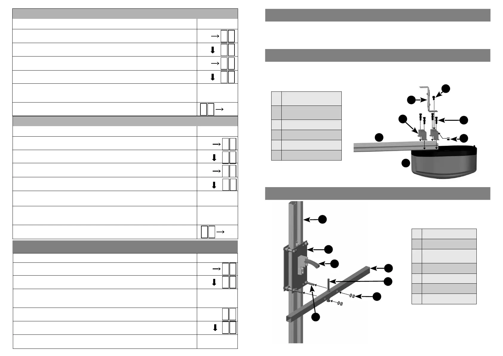
ATTACHING THE POWER HEAD TO THE DRIVE CHANNEL
ATTACHING THE CROSS TUBE TO THE DRIVE CHANNEL
Aach the Power Head to the Drive Channel using the U-Brackets and the four M6 x 25mm hex bolts and
washers provided.
Aach the Floang Bracket to the top most U-Bracket (as shown below) using the M6 x 12mm bolt, nut and
washer.
1
M6 x 12mm
Hex Bolt, Nut & Washer
2
M6 x 25mm
Hex Bolts & Washers
3 Floang Bracket
4 U-Brackets
5 Drive Channel
6 Power Head
1 Drive Channel
2 Liing Assembly
3
Manual Release
Mechanism
4 Cross Tube
5 Adjustable End Stop
6 M8 Nut & Washer (x2)
7 M8 Bolt (x2)
The LUX DC12 Vercal Mount Roll Up Operator is used to operate either single or double roll up garage doors. If a
single door is to be automated, the drive channel will be mounted on either the le or right hand side of the door.
If two doors are being automated, the drive channel will be mounted in the middle, between the two doors.
VERTICAL MOUNT ROLL UP DRIVE CHANNEL POSITION
7
 Loading...