.........................................................................Output opons available (connued):
a) Auxiliary Status (AS):
This output indicates the ‘door status’. * It can be connected to an external LED to
indicate if the door is open or closed and if the baery is charging. It can also be
connected to a GSM device for remote monitoring.
From the Auxiliary Output Menu (AU), press the UP or DOWN buons unl reaching
AS. Press SET to select.
* This is an indicaon of the motor status and not the physical door. If the door is in override or disconnected,
regardless of it’s physical posion, the AS will indicate the status of the operator.
Auxiliary Output (AU) is a single connector and only one Auxiliary Output opon can be selected.
1) Ensure the baery is connected to the Operator.
2) Press the SET buon to enter the Programming Menu (Pr).
3) Press the DOWN buon unl the Lock Menu (LC) is visible.
4) Press the SET buon to enter the Lock Menu.
5) Press the UP and DOWN buons to select the lock type.
PL - Magnec / Power Lock
EL - Electric / Strike Lock
or
OF - Disable the Lock output
6) Press the SET buon to select the lock type (PL or EL) or to disable the lock output
(OF).
L C
SET
SET
p r
SET
ENABLE or DISABLE ELECTRIC/MAGNETIC LOCK ....Menu 6
PROGRAMMING REMOTES ....Menu 7
PROGRAMMING A REMOTE BUTTON TO TRIGGER THE OPERATOR
1) Ensure the baery is connected to the Operator.
2) Press the SET buon to enter the Programming Menu (Pr).
3) Press the DOWN buon unl the Remote Menu (rc) is visible.
4) Press the SET buon to enter the Remote Menu. The display will change to LE
(Learn).
5) To program a remote, press and hold the remote buon that is to be used to trigger
the operator.
6) While holding the remote buon, press the SET buon on the operator. The display
will indicate the stored posion that the newly programmed remote holds (01 to
64). The remote buon has now been programmed.
7) To connue programming remotes, repeat steps 5 and 6 while the menu remains on
LE.
8) To exit LE, use the UP or DOWN buons to scroll to bc and press the SET buon. This
will return you to the Programming Menu (Pr).
9) To exit the Programming Menu (Pr), scroll again to bc and press the SET buon.
R c
SET
p r
SET
L E
SET
b c
SET
b c
16
ATTACHING DOOR U-BRACKETS
Step 1:
Using the Manual Release
Mechanism, release the Liing
Assembly (2) and allow it to gently
come to rest at the boom of the
Drive Channel (1).
Item (3): Cross Tube
2
3
1
Step 2:
Slide the two Door U-Brackets (1)
onto the Door Liing Tube (2).
Note: one Door Liing tube and two
U-Brackets per door (if doing a double
door automaon).
21
9
1 2
Step 3:
Slide the Door Liing Tube/s (1) into
the Cross Tube (2).
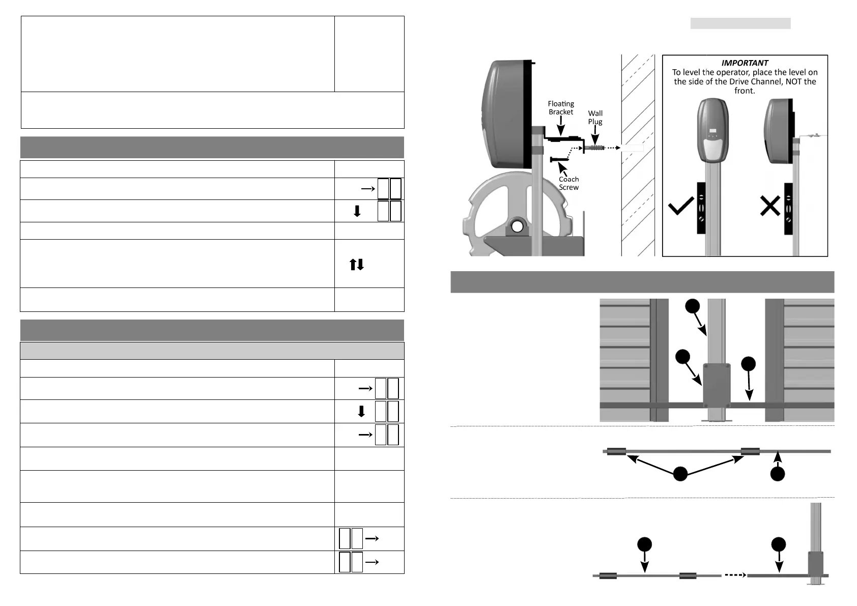
Step 2: Fastening the Floang Bracket to the wall (Single & Double Door):
●
With the operator level, lightly tap the supplied wall plug into the hole drilled in step 1.
●
Ensure the operator is vercally level by placing a spirit level against the side of the Drive Channel.
●
Fasten the Floang Bracket to the wall with the supplied coach screw.
 Loading...