13
Ground
Power
Input
Blower
Output
GREEN
WHITE
BLACK
Installation Instructions
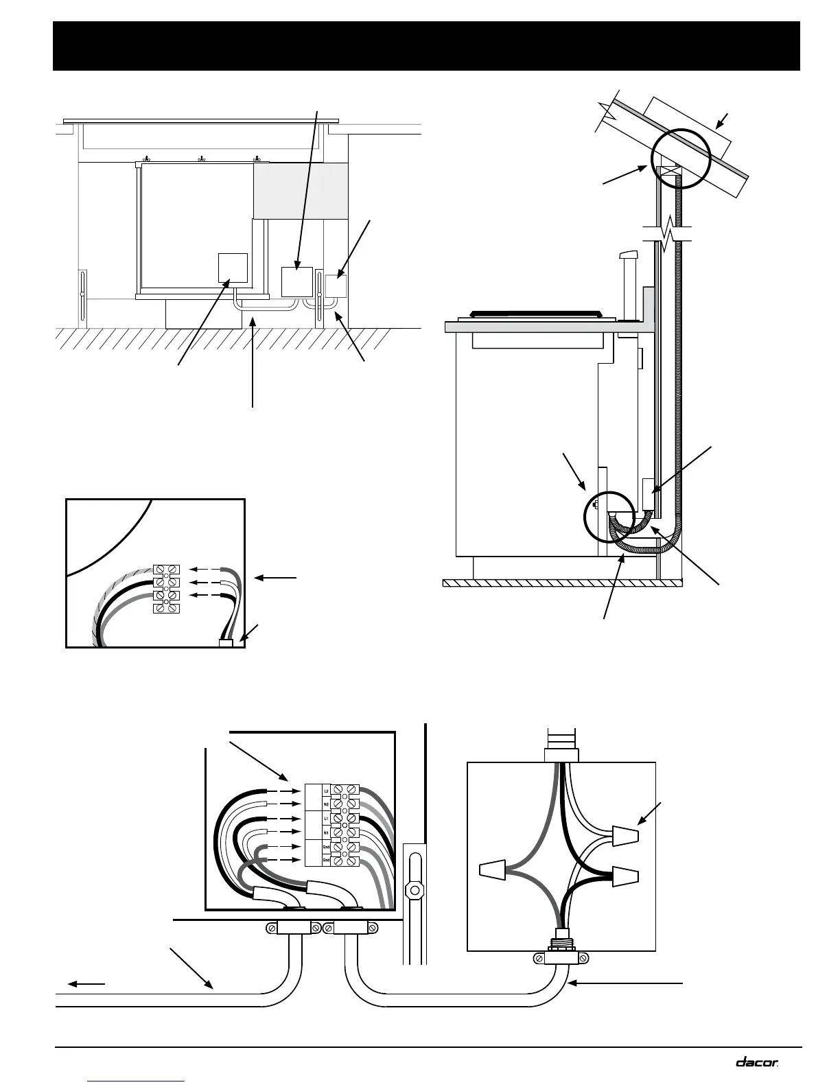
Connect wires/conduit
according to remote or in-line
blower installation instructions
To circuit breaker
panel or fuse box
Connect wires to
Power Input terminals
on raised vent
Black = L1
White = N1
Green - Gnd
Black = L2
White = N2
Green - Gnd
Wiring to Blower Output
terminals on raised vent
Blower power from
Blower Output
terminals on raised
vent to blower
(all types)
Black = L2
White = N2
Green - Gnd
Junction
box
Raised vent
electrical terminals
Raised vent
electrical panel
CABP3
electrical panel
Wire nut,
3 places
To blower
Electrical Wiring - Remote or In-line Blower
Installations (ILHSF or REMP series)
REMP series
blower shown
Floor
Raised vent
electrical
connections -
see Wiring
Diagram B
Raised vent electrical connections -
see Wiring Diagram B
Junction
box
Junction
box
Power supply wiring from raised
vent to remote or in-line blower
Electrical wiring
from raised vent
to junction box
Power supply wiring from
junction to raised vent
Electrical Wiring - Cabinet Blower Installations
(CABP3)
Wiring Diagram B - Raised Vent Electrical Connections
Wiring Diagram A - Electrical Connections for
CABP3 Blower
Cabinet blower
(CABP3)
Power supply wiring from raised
vent to CABP3 blower
Blower electrical connections
- see Wiring Diagram A