H
Holly SampsonAug 18, 2025
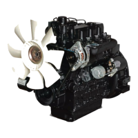
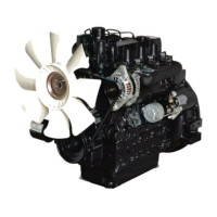
Why is the oil pressure low in my Daedong 4A200B?
- Rryan14Aug 18, 2025
Low oil pressure in your Daedong Engine can stem from several causes. First, ensure the engine oil level is sufficient and replenish if needed. Check the oil strainer for clogs and clean it. Replace a clogged oil filter cartridge. The relief valve might be stuck with dirt, requiring cleaning, or its spring may be weakened or broken, needing replacement. Excessive oil clearance in the crankshaft bearing, crank pin bearing, or rocker arm bushing may necessitate replacement. A closed oil passage needs cleaning. Ensure you are using the specified type of oil. Finally, the oil pump itself might be defective, requiring repair or replacement.