6
ADJUSTMENTS
TAPE ALIGNMENT CHART
Step Item Reference Value Test Tape Adjust Point Test Point Note FIG.
1
Tape Speed
Adjustment
Normal
3,015~3,025Hz MTT-111N RV601
Line Out L/R
Channel
Confirm Wow & Flut-
ter is within 0.35%
FIG.1
3,000~3,010Hz MTT-111N RV601
Line Out L/R
Channel
Confirm Tape Speed
of end position after
adjustment at tape
start position
FIG.1
High 5,820~6,180Hz MTT-111N - - - - - -
Shorted
TP601,
TP602
Confirm High speed
after normal speed
adjustment
FIG.1
2 Azimuth Adjustment
Maximum Level
Phase:Within90°
MTT-114N Head Screw
Line Out L/R
Channel
FIG.2,3,4
3
Recording Bias Oscilla-
tor Frequency Adjust-
ment
80 KHz± 0.5
MTT-5511 L603
TP603,GND
Adjust with frequency
counter connected. FIG.1
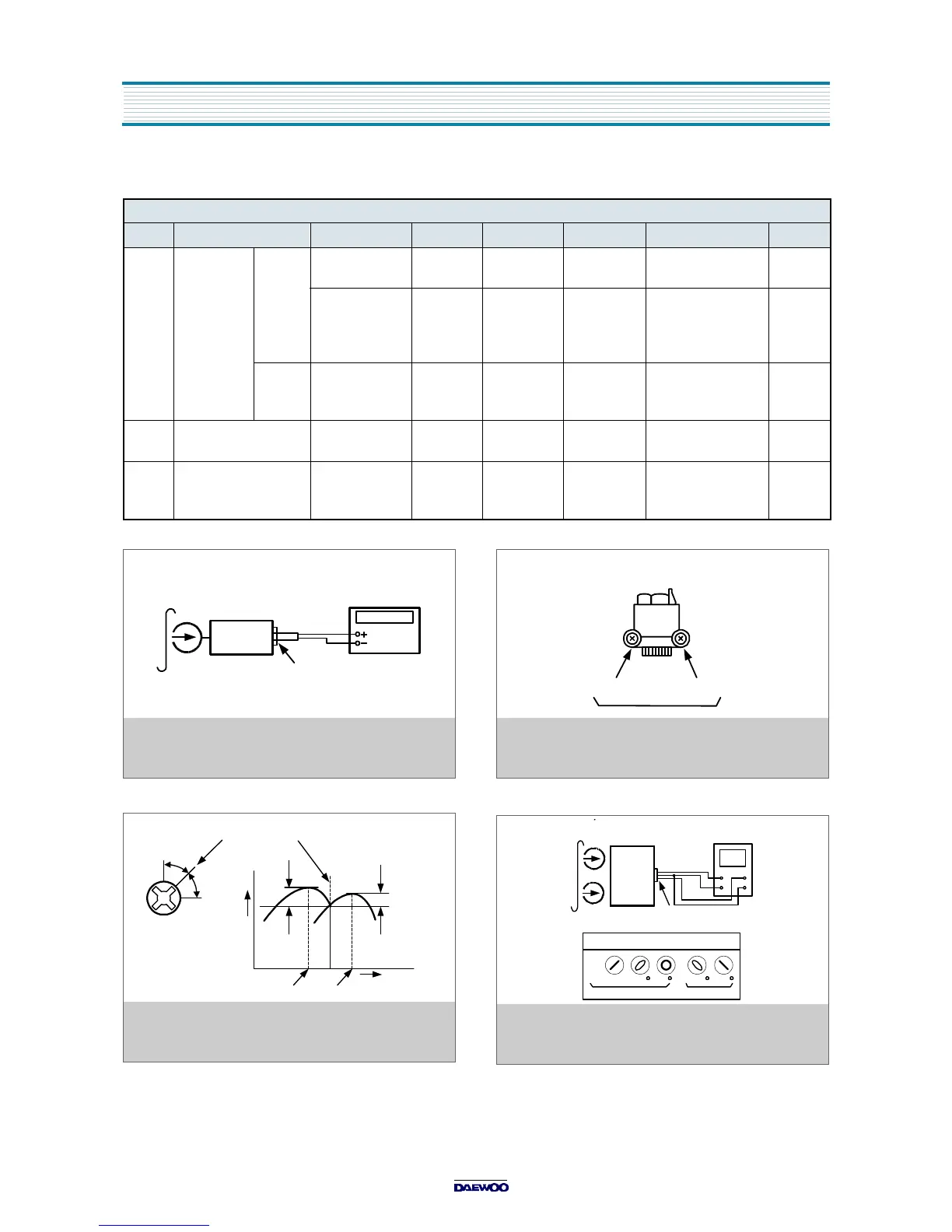
FIG. 1 : Tape Speed & Record Bias Oscillator
Frequency Adjust Circuit
Test Tape : MTT-111N(3kHz)
MTT-5511(Blank)
Output Level
Measurement Point
Set
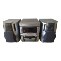
FIG. 2 : Tape Azimuth Adjust Location
(Record/Playback Head)
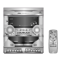
FIG. 3 : Tape Azimuth Adjust Head Screw & Waveform
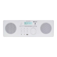
FIG. 4 : Tape Azimuth Adjust Circuit & Waveform
Forward
Side
Reverse
Side
Adjust with Frequency
Counter Connected
L-CH
Peak
R-CH
Peak
Screw
Angle
Output Level
within
1 dB
within
1 dB
L-CH
Peak
R-CH
Peak
Screw Angle
V H
Oscilloscope
L-CH
Output Level
Measurement Point
Set