3
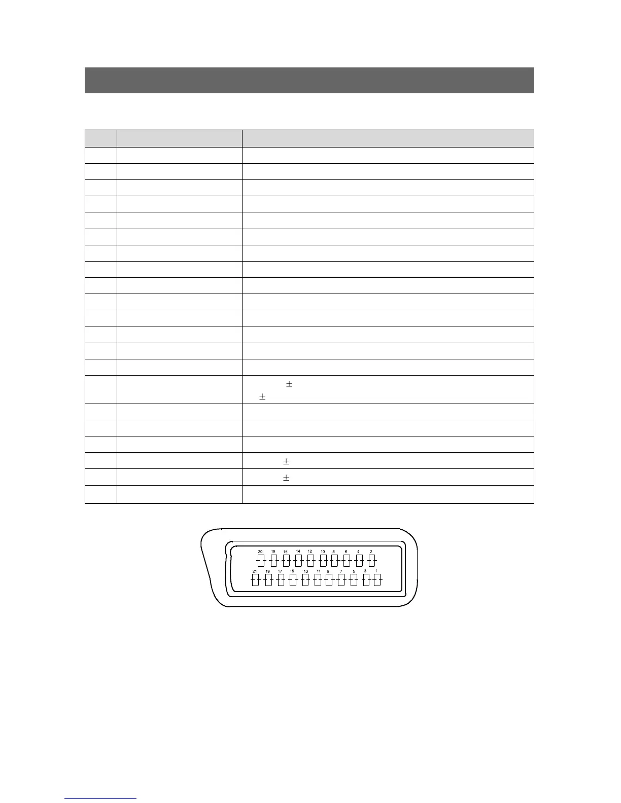
PIN SIGNAL DESCRIPTION MATCHING VALUE
1 Audio Output Right 0.5 Vrms, Impedance < 1kΩ, (RF 54% Mod)
2 Audio Input Right 0.5Vrms, Impedance > 10kΩ
3 Audio Output Left 0.5 Vrms, Impedance < 1kΩ, (RF 54% Mod)
4 Audio Earth
5 Blue Earth
6 Audio Input Left 0.5Vrms, Impedance > 10kΩ
7 Blue Input 0.7Vpp + 0.1V, Inpedance 75Ω
8 Slow Switching TV : 0 to 2V, AV : 4.5 to 12V, Impedance > 10kΩ
9 Green Earth
10 N.C
11 Green Input 0.7Vpp + 0.1V, Impedance 75Ω
12 N.C
13 Red Earth
14 Blanking Earth
15 Red Input 0.7Vpp
0.1V, Impedance 75Ω
Chroma Input 3dB for a luminance signal of 1 Vpp
16 Fast Switching 0 to 0.4V : Logic :"0", 1 to 3V : Logic "1", Impedance 75Ω
17 Video Out Earth
18 Video In Earth
19 Video Output 1 Vpp 3dB, Impedance 75Ω
20 Video Input 1 Vpp 3dB, Impedance 75Ω
21 Common Earth
21Pin EURO-SCART
SPECIFICATIONS
 Loading...