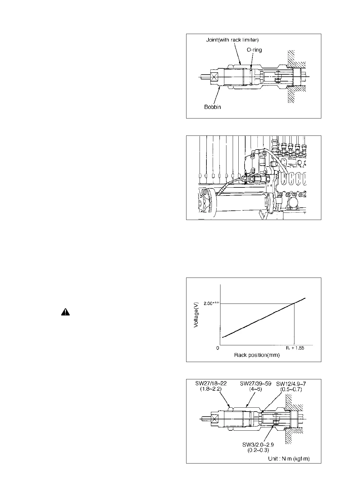
(5) Screw in the bobbin until the edge of
the bobbin contacts the bottom of the
joint.
Note : Before installing the bobbin
in the joint, apply grease to
the O-ring.
- 130 -
EA2M4027
10) Rack sensor adjustment
(1) Secure the control lever in the full
speed position.
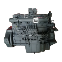
(2) Specified output voltage
Read the specified output voltage and
the specified rack position from the
Rack position - Voltage graph in the
calibration data.
(3) Read the pump speed that corre-
sponds to the specified rack position
from the governor graph of the fuel
injection quantity adjustment table
(page 1 of the data sheet) and set the
pump speed to the speed specified.
EA2M4028
(4) Then, adjust the depth that the bob-
bin is screwed in so that the rack sen-
sor output voltage is 2.00
L
0.01 V.
COUTION : The values at left
vary with the pump.
Refer to the data
sheet at adjustment.
EA2M4029
(5) After adjustment, tighten the bobbin
using the nut.
(6) Move the pump’s lever 2~3 times and
confirm that the voltage is 2.00
L
0.01
V when it is returned to the full posi-
tion.
EA2M4030