6) Coat the push rod with engine oil and
insert it into the push rod hole.
7) Mount the rocker arm assembly on the
cylinder head and tighten the rocker
arm bracket fixing bolts to specified
torque(4.4kg
•
m).
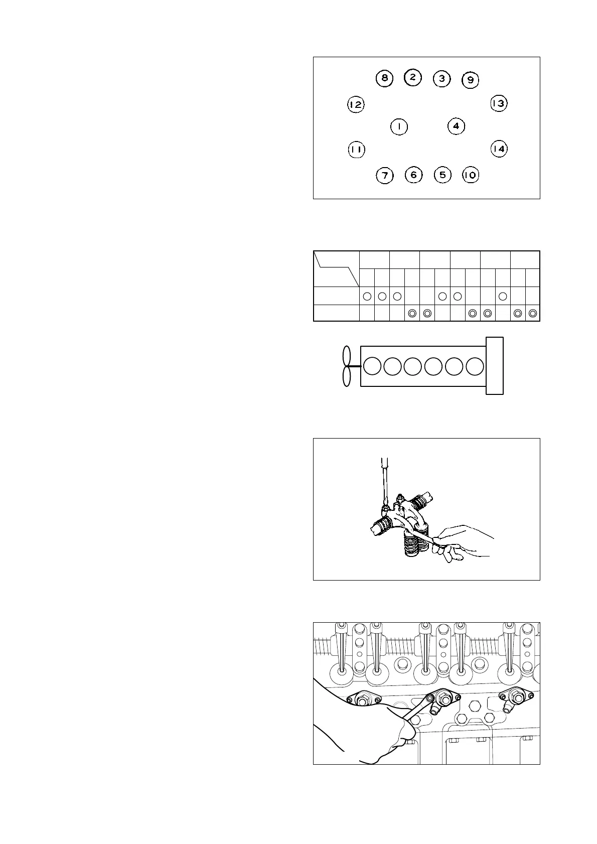
8) Adjust the valve clearance.
•
Guide for valve clearance adjustment
- Place No. 1 piston in the "OT" position
and adjust valve clearance at six posi-
tions as shown in th right-hand figure.
At this time, the intake and exhaust
valves of No. 6 cylinder are in an over-
lapped state.
- Turn the crank 360 degrees to bring the
No. 6 piston in the "OT" position, then
adjust the remaining valve clearance.
- Determine the sequence of the cylinders
and intake/exhaust valves beginning
with the flywheel housing size.
- Intake valve clearance : 0.3mm
- Exhaust valve clearance : 0.3mm
9) Adjust valve clearance with a feeler
gauge and tighten the fixing nuts to
specified torque(4.4kg
•
m).
- 71 -
EQM3082I
EDM1003S
EQM3083I
<Tightening sequence of cylinder head fixing
bolts>
ENGINE TOP VIEW
•
Cylinder No.
Cylinder No.
123456
IN EX IN EX IN EX IN EX IN EX IN EX
No. 1 TDC
No. 6 TDC
Adjusting
valve
3.3.23. Injection nozzle
1) Install the dust seal with its round portion
facing downward.
2) Mount a seal ring(0.5mm) on the seal
ring seating surface of the nozzle tube
and assemble it with the stud bolt with
the nozzle pipe installing direction facing
outward.
3) Be sure to follow the specified torque
(1.0kg
•
m).
Flywheel housing side
Cooling fan side