Do you have a question about the Daewoo DSB-071AH and is the answer not in the manual?
Detailed technical specifications for various Daewoo air conditioner models, covering electrical and physical data.
Diagrams illustrating the dimensions and parts of the indoor unit.
Diagrams showing dimensions and placement for installation plates.
Diagrams illustrating the dimensions and parts of the outdoor unit.
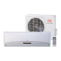
Identifies and describes the parts and functions of the indoor and outdoor units.
Explains the buttons and functions of the remote controller.
Details the refrigerant cycle and provides pressure tables for operation.
Step-by-step guides for disassembling the indoor and outdoor units.
Comprehensive lists of parts for indoor and outdoor units, including codes and specifications.
Details the assembly and components of the indoor unit's control box.
Step-by-step guide to diagnose and resolve common operational issues.
Explains how the unit performs self-diagnosis and error code display patterns.
Provides circuit diagrams for various system functions.
Details key electronic components like MICOM, regulators, and drivers with their functions.
| Type | Split System |
|---|---|
| Refrigerant | R410A |
| Power Supply | 220-240V, 50Hz |
| Air Flow (High) | 380 m³/h |
| Noise Level (Indoor) | 38 dB(A) |
| Cooling Capacity | 7000 BTU/h |
| Power Consumption (Cooling) | 650W |
| Net Weight | 8 Kg |