Do you have a question about the Daewoo DSB-090L and is the answer not in the manual?
Detailed technical specifications for the DSB-090L model, including power, capacity, and dimensions.
Detailed technical specifications for the DSB-120L model, including power, capacity, and dimensions.
Detailed technical specifications for the DSA-100L model, including power, capacity, and dimensions.
Detailed technical specifications for the DSA-120L model, including power, capacity, and dimensions.
Diagrams illustrating the physical dimensions and external features of the indoor unit.
Diagrams illustrating the physical dimensions and external features of the outdoor unit.
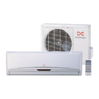
Identification and description of key parts and their functions for both indoor and outdoor units.
Explanation of the remote controller buttons, display, and basic operation.
Details on various operating modes, functions like timers, fan speed, and special operations.
List of main electrical components for DSB and DSA model series, including part codes and specifications.
Schematic diagram illustrating the complete electrical connections and components of the air conditioner.
Flowcharts and error code explanations to diagnose and resolve common operational issues.
Detailed circuit diagrams and explanations for various PCB modules, including power, sensors, and control.
Steps and flow charts for testing the functionality and display of the remote controller's LCD panel.
Methodology for testing the overall functional performance of the remote controller assembly.
Detailed pin configuration and function description for the main microcontroller (MICOM) chip.
Schematics and descriptions for Darlington arrays and voltage regulator ICs used in the circuit.
Circuit details for the reset IC and photo triac components.
Step-by-step instructions and diagrams for disassembling the indoor unit.
Step-by-step instructions and diagrams for disassembling the outdoor unit.
Diagram and parts list for the control box assembly and its components.
| Type | Split System |
|---|---|
| Cooling Capacity | 9000 BTU/h |
| Refrigerant | R410A |
| Power Supply | 220-240V, 50Hz |
| Net Weight (Indoor Unit) | 8 kg |
| Net Weight (Outdoor Unit) | 25 kg |
| Weight | Indoor: 8 kg |
| Operating Temperature (Cooling) | 18°C to 43°C |
| Dimensions (Outdoor Unit) | 700 x 490 x 240 mm |