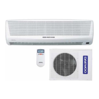
Do you have a question about the Daewoo DSB-240LH-R and is the answer not in the manual?
Technical specifications for DSB-070LH and DSB-071LH models.
Technical specifications for DSB-091LH and DSB-092LH models.
Technical specifications for DSB-121LH and DSB-122LH models.
Technical specifications for DSB-123LH model.
Technical specifications for DSB-182LH model.
Technical specifications for DSB-182LH-R model.
Technical specifications for DSA-183LH-R model.
Technical specifications for DSB-240LH-R model.
Technical specifications for DSA-240LH-R model.
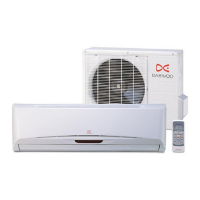
Physical dimensions and layout of the indoor unit for various models.
Physical dimensions and layout of the outdoor unit for various models.
Details the names and functions of components within the indoor unit.
Details the names and functions of components within the outdoor unit.
Identifies and describes the function of each button on the remote controller.
Explains the various indicators shown on the remote controller's display.
Details the operation of ON-Timer and OFF-Timer modes.
Explains the functionality of Sleep, Emergency, Auto, Dehumidification, and Quick modes.
Covers fan speed settings and air discharge direction adjustments.
Describes the frost prevention mechanism for the indoor unit.
Provides wiring diagrams for various indoor unit models.
Provides wiring diagrams for various outdoor unit models.
Details the refrigerant cycle specifications and charge quantities for different models.
Illustrates the control block diagram for specific Daewoo AC models.
Control block diagram for a range of Daewoo AC models.
Provides a flowchart for diagnosing unit operational problems.
Covers notes, error codes, and troubleshooting for specific issues like non-operation.
Details the pin configuration and functions of the MICOM (Microcontroller) unit.
Describes the function and pinout of KID65004 Darlington Arrays.
Explains the KIA7805P (5VDC) and KIA7812P (12VDC) regulators.
Details the KIA7042P reset integrated circuit and its function.
Step-by-step guide for disassembling the indoor unit.
Step-by-step guide for disassembling the outdoor unit.
Visual breakdown of indoor unit components with part numbers.
Visual breakdown of outdoor unit components with part numbers.
Exploded view and parts list for the control box assembly.
| Cooling Capacity | 24000 BTU/h |
|---|---|
| Refrigerant | R410A |
| Power Supply | 220-240V, 50Hz |
| Type | Split System |
| Operating Temperature (Cooling) | 18°C to 43°C |