Some disassembly is required to access the adjustment locations. Refer to the "Disassembly Selection" in this publication
for disassembly instructions.
Caution : Use an isolation transformer when servicing.
5. Mechanical Checks/Gear Alignment (fig. 1, 2, 3, 4, 5)
When mechanical problems occur or when reassembling parts in this mechanism, be sure to confirm the following instruc-
tions to confirm the following:
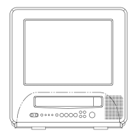
1. Make sure that the datum hole of the cam gear "A" is aligned with the hole "B" in the main base in the EJECT mode
(fig. 1)
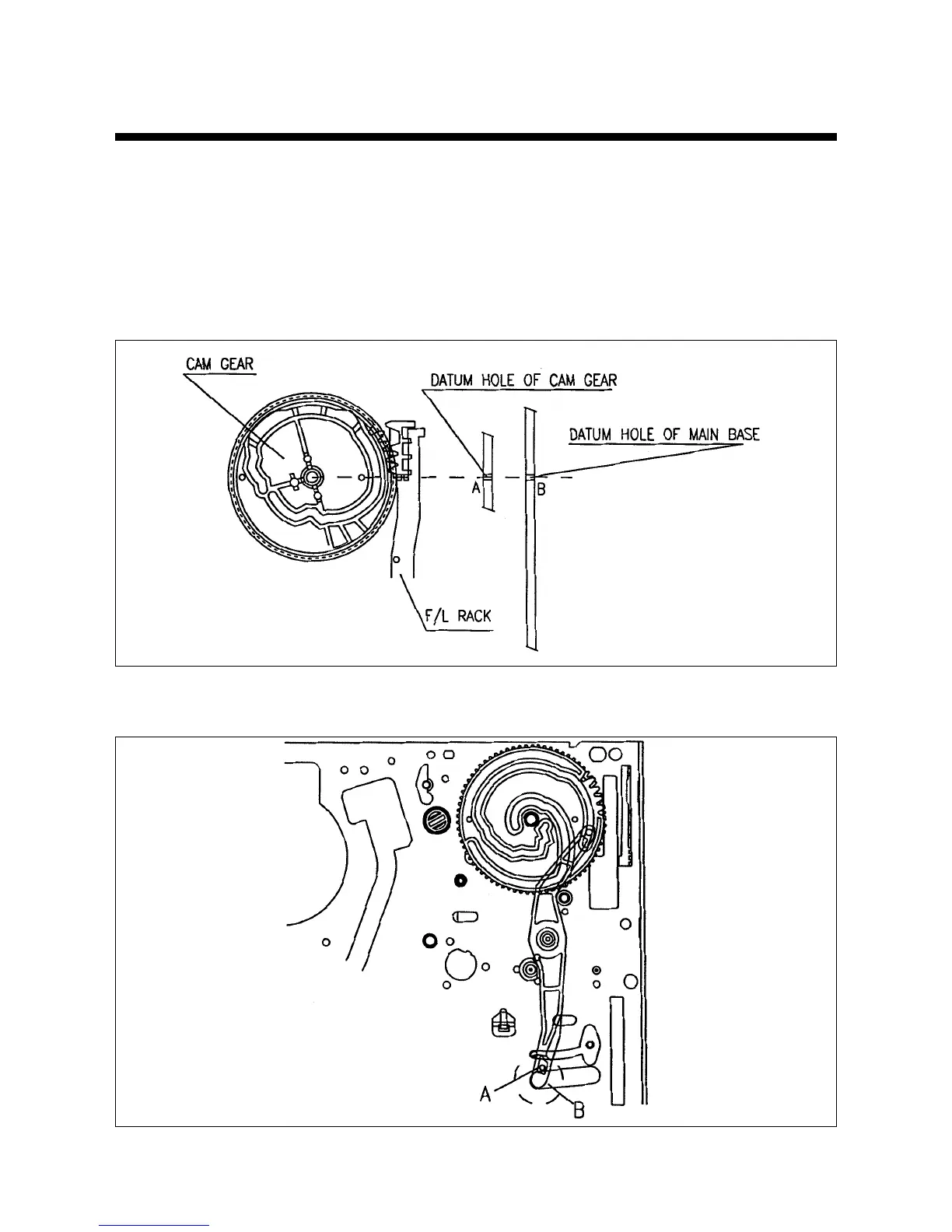
2. Make sure that the part of the relay lever "A" which is assembled with CONNECT PLATE is fully rotated up to the left and
of the hole "B" (Fig. 2)
17
Fig. 1– Mechanical Checks/Cam Gear and F/L Alignmen
Fig. 2- Mechanical Checks/relay Lever and Cam Gear Alinment