Do you have a question about the Daewoo DVQ-13H1FCN and is the answer not in the manual?
Detailed guidelines to prevent fire and electrical shock hazards during servicing.
Precautions and procedures to mitigate X-radiation risks from CRTs.
Safety measures to prevent picture tube implosion during handling and installation.
Guidelines for safe and optimal installation of the TV/VCR unit.
Illustrates electrical connections between various PCBs and components.
Procedures for entering and performing service mode adjustments.
Step-by-step guide for essential adjustments during product assembly.
Specific alignment procedures for the VCR deck mechanism.
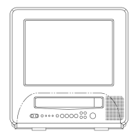
Visual breakdown of parts for model DVQ-19H2FCN.
Visual breakdown of parts for model DVQ-19H1FC.
Visual breakdown of parts for model DVQ-13H2FC.
Visual breakdown of parts for model DVQ-13H1FC.
List of optional or model-specific replacement parts.
Detailed pin description and function of ICS01 IC.
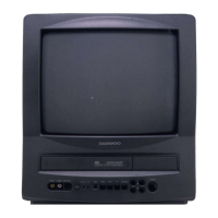
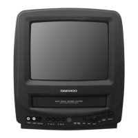
Overview of the TV/VCR system's key features and capabilities.
Description and pinout for the power control module.
Diagnostic steps for troubleshooting power-related issues.
Troubleshooting steps for diagnosing picture display problems.
Troubleshooting steps for diagnosing audio output issues.
Diagnostic procedures for channel tuning or reception failures.
Troubleshooting guide for color reproduction problems.
Steps to diagnose and fix vertical display issues.
Troubleshooting steps for missing or faulty on-screen display.
Steps to diagnose and resolve remote control malfunctions.
Troubleshooting steps for cassette loading mechanism errors.
Diagnostic procedures for drum or capstan rotation failures.
Steps to troubleshoot VCR picture playback issues.
Troubleshooting guide for color problems during VCR playback.
Steps to diagnose and fix audio issues during VCR playback.
Troubleshooting steps for VCR recording picture failures.
Troubleshooting guide for VCR recording audio problems.
Steps to diagnose issues with external input signals.
| Brand | Daewoo |
|---|---|
| Model | DVQ-13H1FCN |
| Category | TV VCR Combo |
| Language | English |