ALIGNMENT INSTRUCTIONS
2. ASSEMBLY ADJUSTMENTS
1) SCREEN ADJUSTMENT(S2)
w
Enter the service mode and select service adjustment S2
w
You can see the horizontal straight line on the screen
w
Adjust the Screen Control volume(located on FBT) so that the horizontal straight line on screen may be disappear.
w
Press the MENU button to exit the screen adjustment mode.
2) FOCUS ADJUSTMENT(S2)
w
Turn in a local station and the Focus Control volume(located on FBT) for best picture details at light condition.
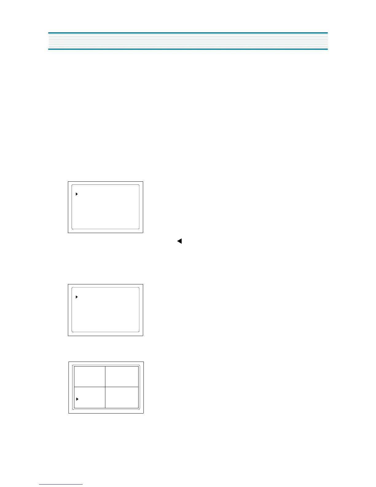
3) RF-AGC ADJUSTMENT(S5)
w
Receive a good local channel.
w
Enter the service mode and select service adjustment S5
w
You can see the OSD as shown in below.
w
Select AGC item, press volume up (
U
) or down( ) buttons until noise or beet in picture disappears.
4) GEOMETRIC ADJUSTMENT(S6)
w
Enter the service mode and select service adjustment S6
w
You can see the OSD as shown in below.
w
Use the CH up ( s ) or down ( t ) buttons to select "CROSS BW" item.
w
Use the VOL up (
U
) button to select internal cross pattern.
AGC Auto
IF CONTROL
AGC Vol 3.75V
AGC 000
VIDEO LEV
005 FM LEV
007
HFREQ 012
CROSS BW
H CENTER
GEOMETRY
V SIZE 060
V CENTER 040
V SC
020 V LIN
000
NO SD POWER OFF NO
CROSS BW
020
HBLKR 1 HBLKL 6
H CENTER
GEOMETRY
V SIZE 060
V CENTER 040
V SC
020
V LIN
000
NO SD POWER OFF NO
CROSS BW
020
HBLKR 1 HBLKL 6
- Figure1 -
10
 Loading...