4242
2. REC mode
•
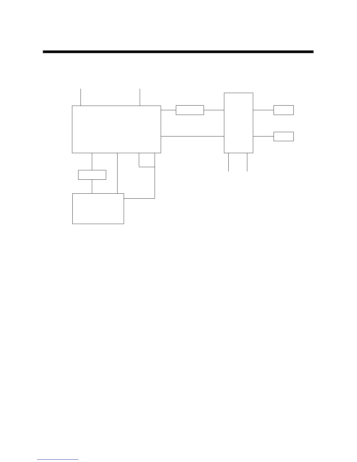
Signal is put in to #31 of IY01(LA7423A), and it is seperated into Luminance and Chroma within IC.FM modulated
luminance signal is put in to #34 and low-frequency transformed color signal is put in to #14.
After passing through REC EQ, circuit for adjusting REC characteristics, FM modulated signal is put in to
IY03(LA7411)#8 and color signal put out to #11 is put in to IY03 #3.
•
The signal put in to #7, #8 of IY03(LA7411) is recorded on the tape by HEAD through AGC and REC CUR
RENT AMP.
3. PB Mode
•
In case of SP, the signals on #17, #20 of IY03(LA7411) are amplified to 60dB respectively by V.SW, put out
to #7 IY03 and put in to #4 IY01(LA7423A)
•
FM signal put in to #14 of IY01 is demodulated at FM DEMODULATIOR after passing through FM EQ.
within IC and put in to Y/C MIXER after passing through 3.0MHz LPF to eliminate color signal component.
•
While FM signal put in to #14 of IY01 is passing through 1.3MHz LPF. Only low-frequency transformed color
signal passes.
The color signal is converted to 3.58MHz at Main CONVERTER and is put in to Y/C MIXER after it's
amplified to 6dB and goes through ACC/BURST EMPHASIS. Y/C signal is put out to #28.
VIDEO OUT
HA SW REC "H"
7.1M LPF
41
IY02 8
LC89960
IH CCD IC
REC EQ R/T
R/T
VIDEO IN
31 28
IY01
LA7423A
Y/C PROCESS IC
9111718
IY03
LA7411
814
PRE-AMP
IC
715
14
 Loading...