35 36
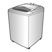
3. DETAIL EXPLANATION OF HEATER PARTS
• In case MICOM terminal No. 8 is “L”, Q6 is off and Q7 is on, and Heater is drived by RELAY.
• D3 prevents Q7 from reverse voltage of coil when RELAY is off.
• RELAY of heater unit is drived by DC 9V. DC 9V is supplied from REGULATOR PQ09RF1.
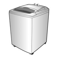
• The waveform of MICOM No.8 is as follows.
BLACK
BLACK
VOLTAGE
ACTION STOPSTOP
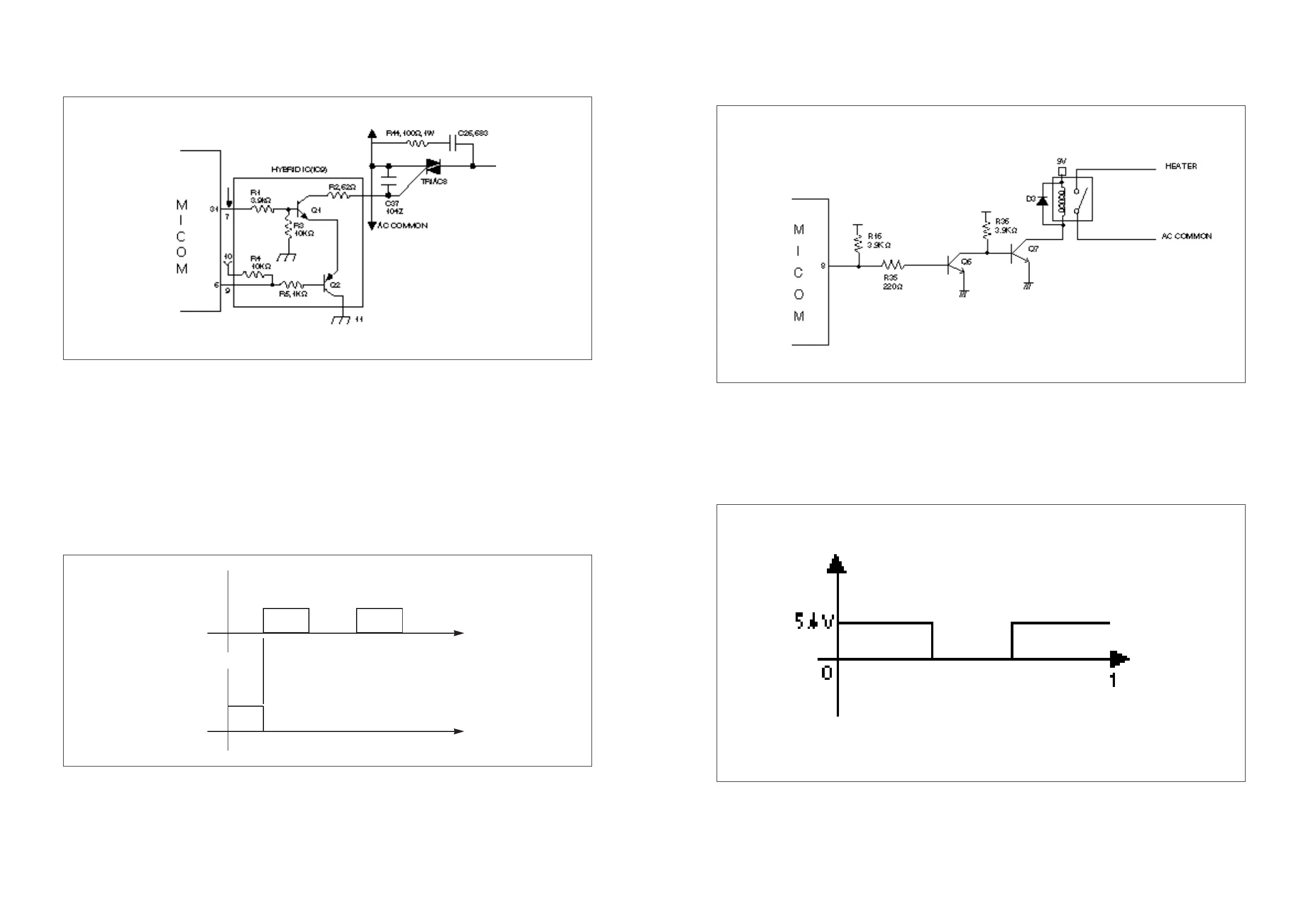
2. DETAIL EXPLANATION OF CIRCUIT ACTION (ACTION OF CW WASH)
• In case MICOM terminal No. 31 is ‘H’ and No. 6 is ‘L’ the Q1 (KTN2222S) & the Q2 (KTA1664) turn on
and control the TRIAC. The resistance, as 62Ω & 1/2W, of the R52 is used to limit the GATE current of
the TRIAC.
• The resistance R1(3.9KΩ, 1/4W) and the R5(1KΩ, 1/4W) control the base current of the Q1 & Q2 in
order as TR forces to turn on sufficiently.
• The ceramic condenser C29 between the T1 and the GATE of the TRIAC8 is used for preventing the
wrong action by means of the noise.
• The R63(100Ω, 1W) and C28(683K) between the T1 and T2 of the TRIAC is used for protecting the
TRIAC, it usually called SNUBBER CIRCUIT.
• The waveform of MICOM No. 31 & 6 is as follows.
action
action
stop
5.4V
0V
Terminal No. 31
t
t
Terminal No. 6
5.4V
0V
action