Do you have a question about the Daewoo FR - 590KT and is the answer not in the manual?
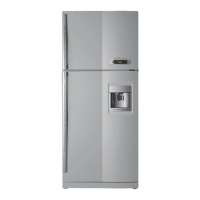
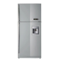
Detailed dimensions for FR-530KT and FR-590KT models, including width, depth, and height.
Summary of key refrigerator specifications including model, capacity, dimensions, and refrigerant type.
Lists various electrical components like compressors and relays, specifying part codes and voltage compatibility.
Details specifications for starting capacitors, including part codes and voltage/capacitance ratings.
Lists specifications for running capacitors, including part codes, rated voltage, and capacitance.
Provides specifications for the F-Fan Motor, including voltage, part code, and revolution speed.
Details specifications for the C-Fan Motor, including voltage, part code, and revolution speed.
Lists specifications for the defrost heater, including voltage, wattage, and part code.
Specifies part codes and colors for the lamp assembly.
Lists specifications for the main PCB assembly, including type name and part code.
Details specifications for the dryer, including capacity (g) and part code.
Lists specifications for the PCB fuse, including voltage, rated current, and part code.
Provides specifications for the thermostat fuse, including operating temperature and part code.
Lists specifications for the door switch, including voltage and part code.
Details different power cord shapes, part codes, descriptions, and remarks for various countries.
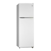
Outlines available door color options based on refrigerant type and finish.
Details temperature regulation for fresh food and freezer compartments, including dial settings and lever control.
Explains temperature control mechanisms, including COMP control, off points, and fan delay.
Describes optional functions like weak refrigeration, middle off points, and fan delay settings.
Explains how the defrosting period is determined and the conditions for initiating defrosting.
Details normal and compulsory defrosting modes, including pre-cool, heater defrosting, pause, and fan delay.
Describes actions taken for low temperatures in compartments, including R-Heater control.
Covers initial defrosting procedures and conditions based on D-Sensor temperature.
Explains compressor restart prevention time and conditions to protect the compressor.
Details the option circuit, specifically for weak refrigeration, related to R-Sensor resistance.
Explains LED error displays, their starting conditions, and how to control or end them.
Shows the electrical connections between various components of the refrigerator.
Provides a detailed schematic of the refrigerator's electronic control circuit, including PCB layout.
Illustrates the path of air circulation within the refrigerator and freezer compartments.
Depicts the flow of refrigerant through the system components, from compressor to evaporator.
Step-by-step instructions for removing the freezer and refrigerator doors.
Procedure for removing and reassembling the refrigerator door handles.
Instructions for removing the freezer louver, including screw covers and the louver itself.
Steps to remove the refrigerator control box, accessing it via the light bulb base.
Guide on how to safely remove and replace the temperature fuse.
Procedure for disassembling the evaporator, including removing screws and disconnecting pipes.
Steps for removing the defrost heater, including wire connectors and the sensor.
Instructions on how to remove the cubic duct using a screwdriver.
Procedure for pulling out the side louver carefully.
Detailed steps for removing the compressor, including cover, relay assembly, and pipes.
Instructions for removing the wire condenser and C-fan assembly, including pipes and motor.
An overall exploded view diagram showing the assembly of all major refrigerator components.
A detailed list of all part codes, names, descriptions, quantities, and remarks for the models.
Exploded view and parts list specifically for the machine room components.
| Brand | Daewoo |
|---|---|
| Model | FR - 590KT |
| Category | Refrigerator |
| Language | English |