Do you have a question about the Daewoo FR-520NT and is the answer not in the manual?
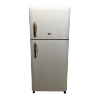
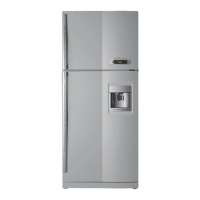
Details external dimensions and named parts for the FR-520NT model.
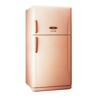
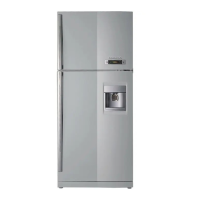
Details external dimensions and named parts for the FR-550NT model.
Provides general specifications, including model name, capacity, dimensions, and refrigerant.
Lists electrical components like compressors, relays, capacitors, and motors with part codes and specifications.
Details various power cord types, their part codes, and intended regions of use.
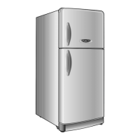
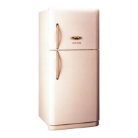
Specifies available door color options and corresponding part codes for different models.
Explains temperature control for fresh food and freezer compartments using levers and sensors.
Details how the compressor and fan are controlled based on R-Sensor readings and operating modes.
Describes options for weak refrigeration, middle off point, on/off difference, and fan delay settings.
Explains the determination and explanation of the defrosting period based on compressor runtime and errors.
Outlines the normal and compulsory defrosting procedures, including pre-cool, heater defrosting, pause, and fan delay.
Describes how the system acts when low temperatures are detected in the compartments.
Details the conditions and behavior of initial defrosting upon power input.
Explains the mechanism to prevent the compressor from restarting immediately after turning off.
Discusses option circuits, specifically for weak refrigeration, involving R-Sensor and switch settings.
Explains error codes (R1, D1, D2, C1) and their corresponding display modes and control methods.
Illustrates the electrical connections and layout of components within the refrigerator.
Provides a simplified or partial view of the wiring connections for clarity.
Shows the detailed electronic circuit schematic of the main control board and associated components.
Depicts the path of air circulation within the refrigerator and freezer compartments.
Illustrates the flow of refrigerant through the cooling system components.
Step-by-step guide for removing and disassembling the freezer louver.
Instructions for removing the control switch assembly from the refrigerator compartment.
A comprehensive exploded view showing all refrigerator components and their assembly.
A detailed list of all parts with part codes, names, descriptions, and quantities.
Focuses on the exploded view and parts list specific to the machine room components.
| Color | White |
|---|---|
| Number of Doors | 2 |
| Defrost System | Manual |
| Type | Top Freezer |
| Total Capacity | 520 liters |
| Cooling System | Direct Cool |
| Width | 70 cm |
| Energy efficiency class | A+ |