Do you have a question about the Daewoo FR - 590NW and is the answer not in the manual?
Important notes regarding part changes and obtaining the latest parts information.
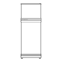
Provides external dimensions for FR-530NT and FR-590NT models.
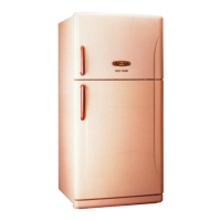
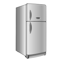
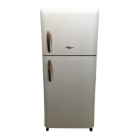
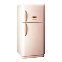
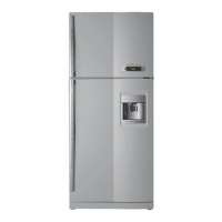
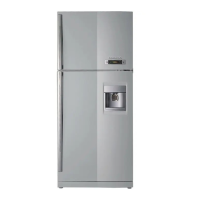
Lists and illustrates all external parts for FR-530NT/FR-590NT and FR-590NW models.
Details model name, capacity, external dimensions, and refrigerant type.
Lists components like compressors, relays, capacitors, and motors with specifications.
Illustrates various power cord types with part codes and regional remarks.
Details available door color types and materials for different models.
Explains the custom LED display and normal state indicators.
Describes temperature control for the freshfood compartment using buttons and sensors.
Covers defrosting period determination and the defrosting mode sequence.
Details error codes, their display, and buzzer alarms for various fault conditions.
Covers forced defrosting, time delays, initial defrosting, delivery, restart, and demonstration.
Illustrates the electrical connections and component layout.
Provides a detailed schematic of the refrigerator's electronic circuit.
Shows the path of air circulation within the refrigerator compartments.
Depicts the refrigerant flow and components in the cooling system.
Step-by-step instructions for removing and installing freezer and refrigerator doors.
Procedure for removing and reassembling door handles and decorators.
Instructions for removing the freezer compartment louver and light bulb cover.
Guide for removing the refrigerator control box and light bulb base.
Steps for safely removing and replacing the temperature fuse.
Procedure for disassembling and removing the evaporator unit.
Instructions for removing the defrost heater and its sensor.
Guide for removing the cubic duct component.
Instructions for removing the side louver component.
Steps for safely removing the front control panel assembly.
Procedure for removing the compressor, including cover, relay, and pipes.
Instructions for removing wire condenser pipes and the C-fan motor.
Illustrated parts breakdown for FR-530NT and FR-590NT models.
Illustrated parts breakdown for the FR-590NW model.
Illustrated parts breakdown for the machine room components.
| Model | FR-590NW |
|---|---|
| Category | Refrigerator |
| Color | White |
| Climate Class | SN-T |
| Voltage | 220-240V |
| Frequency | 50 Hz |
| Shelves Material | Glass |