Do you have a question about the Daewoo FR - 590NT and is the answer not in the manual?
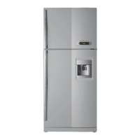
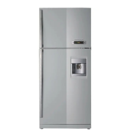
Provides external dimensions for FR-530NT and FR-590NT models.
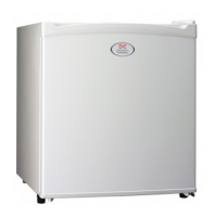
Lists and illustrates the various parts of FR-530NT/FR-590NT and FR-590NW models.
Details electrical components like compressors, relays, capacitors, and motors with specifications.
Illustrates and lists different power cord types, part codes, and their remarks.
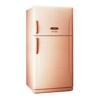
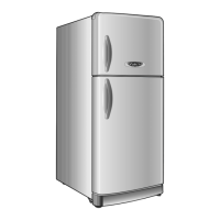
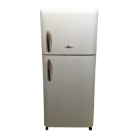
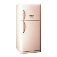
Details color options for freezer and refrigerator doors, categorized by refrigerant type and key type.
Presents a comparative table of specifications for FR-530NT, FR-590NT, and FR-590NW models.
Explains the custom LED display and normal state indicators for refrigerator operation.
Details temperature regulation methods for the freshfood compartment via buttons and sensors.
Describes how to start, stop, and operate the Fuzzy Mode, including its limitations.
Outlines conditions and criteria determining the defrosting period for the refrigerator.
Explains the sequence and control of the defrosting mode, including pre-cool, heater, pause, and fan-delay.
Details how errors are displayed on the C-LED, including error codes and their meanings.
Describes the procedure for initiating a forced defrosting cycle manually.
Explains time delays for fan and other electric devices based on compressor operation and door switches.
Covers the initial defrosting process that occurs upon initial power supply based on sensor readings.
Provides instructions for initial setup and operation after product delivery.
Details the mechanism to prevent the compressor from restarting immediately after shutoff.
Explains the conditions under which the buzzer alarm activates and its patterns.
Describes the procedure to activate and control the demonstration mode for product display.
Details the adjustment of the R-Sensor off-point for specific refrigeration conditions.
Illustrates the electrical connections and layout of components within the refrigerator.
Provides a detailed schematic of the refrigerator's electronic circuit board and connections.
Shows the path of air circulation within the freezer and refrigerator compartments.
Illustrates the flow path of the refrigerant through the cooling system components.
Step-by-step instructions for removing and installing freezer and refrigerator doors.
Guides on how to remove and reattach the refrigerator door handles.
Provides steps to disassemble and reassemble the freezer louver and light bulb cover.
Details the process of removing the refrigerator control box and its components.
Step-by-step guide for replacing the temperature fuse located near the evaporator.
Instructions for safely removing and disconnecting the evaporator unit.
Steps for removing the defrost heater and its associated sensor from the evaporator.
Instructions for removing the cubic duct, emphasizing care to avoid breaking hooks.
Steps to carefully pull out the side louver, avoiding damage to sealing stripes.
Guide on removing the front control panel and its window.
Detailed steps for removing the compressor, including relay assembly and pipes.
Instructions for removing the wire condenser and C-fan assembly.
Comprehensive exploded view and parts list for FR-530NT and FR-590NT models.
Comprehensive exploded view and parts list for the FR-590NW model.
Exploded view and parts list specifically for the machine room components.
| Brand | Daewoo |
|---|---|
| Model | FR - 590NT |
| Category | Refrigerator |
| Language | English |