46
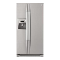
The main-PCB is connected to the Inverter through the Control Input Connection, using the Control Input Cable.
Frequency signal to the IN pin and the 0V to the GND pin (see below Figure)
b. Input Signal
Measure the input signal frequency
with Oscilloscope (Hz).
c. Output Signal
Measure the output signal frequency
with Oscilloscope (Hz).
a. AC Input
Measure the AC input voltage with multi tester
5) Frequency mode connection & Check point
- Inverter AC Input & Input & Output Signal
Main-PCB
INVERTER
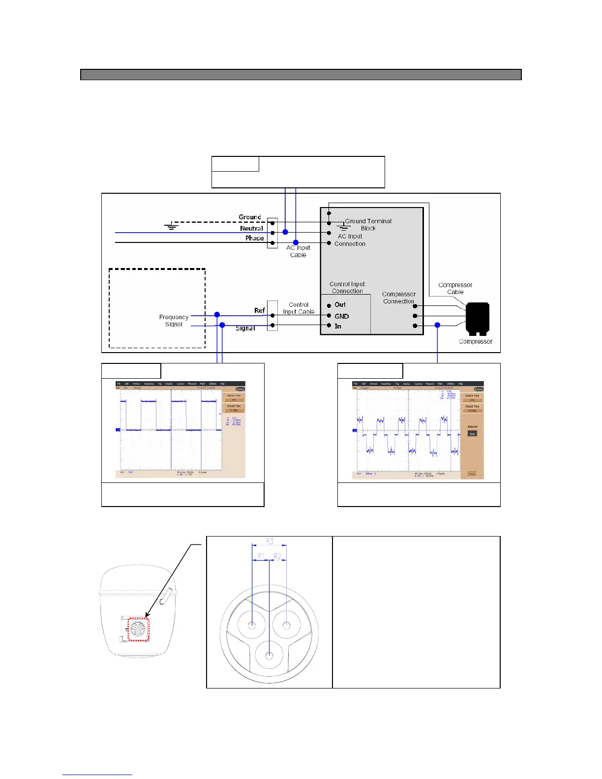
- Compressor Motor Winding
Measure winding for open circuit between
all pair of pins on the hermetic terminal.
1) R1 = R2 = R3
- Compressor Motor Winding is OK.
2) R1, R2, R3 are not same
- Compressor Motor Winding is OPEN.