Do you have a question about the Daewoo FRS-U20DF. and is the answer not in the manual?
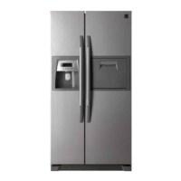
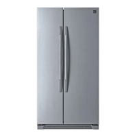
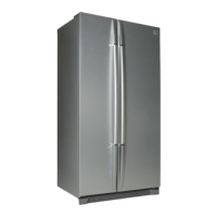
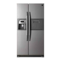
Provides dimensions for U20DF and U20DG refrigerator series.
Identifies and labels internal components of the freezer and refrigerator compartments.
Explains front PCB buttons, display icons, and their respective controls.
Lists error codes, their meanings, and procedures for starting/exiting error display.
Details the flow of ice making, modes, and crusher function for the automatic icemaker.
Explains dispenser modes, display icons, and control flow for crushed/cubed ice and water.
Illustrates the power circuit diagram and lists voltages for various parts.
Details the function, working points, resistance, and voltage for F, R, and D sensors.
Explains the circuit diagram and operation of relays controlled by the MICOM.
Explains frequency mode, compressor speed relation, and input signals for inverter models.
Shows the location of components visible from the front of the refrigerator.
Illustrates component locations within the freezer and refrigerator compartments.
Shows the location of the compressor, inverter controller, condenser, and dryer.
Details the disassembling procedure and resistance check for the ice maker tube assembly.
Provides disassembling steps and resistance check for the geared motor and solenoid valve.
Explains disassembling and checking procedures for the dispenser micro switch.
Lists checks for the main PCB components like cooler, relay, fan, fuse, and regulator.
Details the disassembling procedure and checks for ice dropping motor, sensors, and switches.
Explains frequency mode, compressor speed relation, and input frequencies used.
Guides on diagnosing issues when freezer/refrigerator lights are off and F-PCB power is off.
Diagnoses freezing failures (foods not frozen/cold) by checking components and error codes.
Diagnoses refrigeration failures (foods not cool) by checking components, errors, and door seal.
Covers diagnosis and solutions for compressor operation noise and vibration.
Diagnoses the door opening alarm that continues even when the door is closed.
Outlines heavy repair processes: removing residuals, parts replacement, vacuum, charging, leak testing.
Lists essential precautions for using tools, removing refrigerant, replacing driers, and welding.
Details practical steps for refrigerant removal, nitrogen blowing welding, vacuum degassing, and charging.
Covers checking doorway clearance, finding a suitable place, and installation notes.
Provides procedures for removing and replacing freezer and refrigerator doors.
Guides on installing the water line, checking pressure, connecting parts, and flushing the system.
| Type | Top Freezer Refrigerator |
|---|---|
| Dimensions (H x W x D) | 1780 x 790 x 730 mm |
| Width | 790 mm |
| Height | 1780 mm |
| Depth | 730 mm |