39
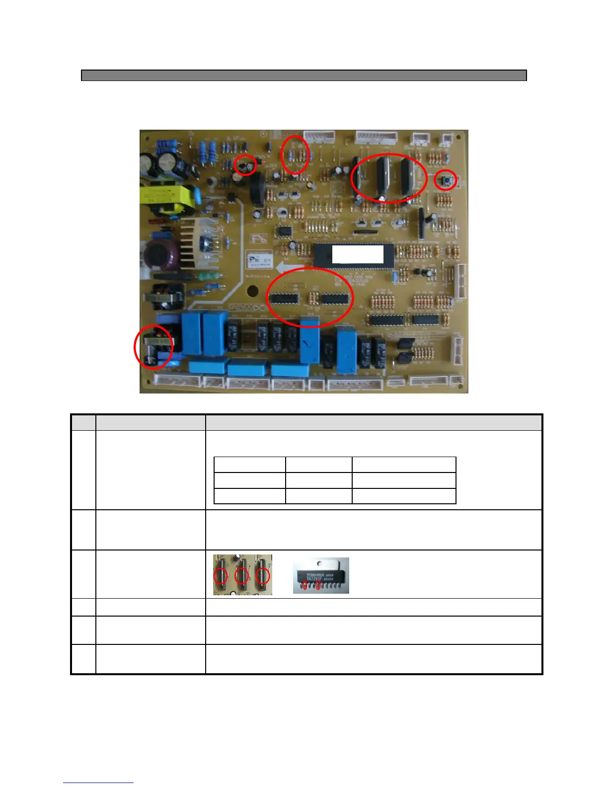
8-5. Main PCB ( None Inverter Compressor models )
1
2
3
4
5
6
MICOM
* Make voltage ( 12V → 5V ) to MICOM.
Voltage check of IC#6 (Input :12V,Output : 5V)
Regulator IC(5V)6
•To check input & output voltage of Fan
▷#2 : Input
▷#5 : Output
* To shorten time in PCB checkup
( 1 time pushing is 1 minute.)
* To check when each device does not work (250V,3.15A)
• Receive signal ( 5V ) from the MICOM.
Deliver signal (12V) each electric device.
▷Check input & output voltage of MICOM and IC7
•When consumer claim about the refrigerator’s temperature follow this.
Change the resistance ( cutting jumper )
Time Shortening
Switch
5
Electric Current Fuse4
Fan Power
Controller
3
Relay Power
Controller
2
Make refrigerator
cooler
1
Check PointItemNo
F R C
down by 3℃J18 & J19Cutting of
down by 1.5℃J18Cutting of
RemarkFRS-U20**