Do you have a question about the Daewoo FRS-U20EF. and is the answer not in the manual?
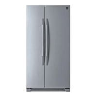
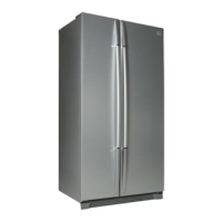
Provides detailed dimensions for specific external views of refrigerator models.
Details external dimensions for U20FF and U20FG series refrigerator models.
Identifies and labels various parts within the freezer and refrigerator compartments.
Details the front PCB buttons, LED display, and their respective functions and controls.
Explains the defrosting cycle, including pre-cool, heater defrosting, pause, and fan-delay for non-inverter models.
Details the defrosting cycle for inverter compressor models, covering pre-cool, heater defrosting, pause, and fan-delay.
Describes the procedure and conditions for initiating a forced defrosting mode for service purposes.
Outlines the voltage specifications for the control modes of the F-FAN, R-FAN, and C-FAN motors.
Details the control logic for the buzzer and various alarm conditions, including door open alarms.
Explains how interior lights in the refrigerator and freezer compartments are controlled by door switches.
Provides instructions on how to start, control, and exit the demonstration mode of the refrigerator.
Explains how to adjust refrigerator compartment temperature by cutting jump wires on the main PCB.
Lists and explains various error codes displayed on the 88 Display CLED and their meanings.
Summarizes various functions, including dial functions, filter information, and water supply adjustments.
Details the flow of ice making, including ice making, separating, water supply, and crusher functions.
Explains the dispenser's initial mode, display icons, and control logic for water, crushed ice, and cubed ice.
Describes the temperature control, stepping motor operation, damper heater control, and error checking for the Magic Cool Zone.
Illustrates the power circuit diagram, showing voltage distribution at various points (A-E).
Details the function, working points, resistance, and sensing voltage for F-sensor, R-sensor, and D-sensor.
Explains the circuit diagram and working conditions (ON/OFF) for various relays controlled by the MICOM.
Explains the operation of the TA7291P drive IC for controlling fan motors (R-FAN, F-FAN, C-FAN).
Details compressor speed control for inverter models based on frequency signals and temperature conditions.
Provides a detailed wiring diagram for non-inverter refrigerator models, showing component connections.
Presents the wiring diagram specific to inverter compressor models, illustrating component interconnections.
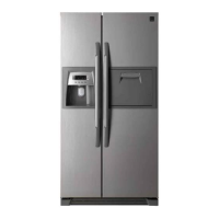
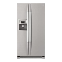
Illustrates the location of major components visible from the front of the refrigerator.
Shows the location of components inside the freezer and refrigerator compartments.
Locates key components such as the D-Sensor, Temp Fuse, Evaporator, and Defrost Heater.
Identifies components within the machine compartment, including the compressor and inverter controller.
Provides a disassembling procedure and checking criteria for the hose ice maker tube assembly.
Details the disassembling procedure and checking criteria for the bracket geared motor assembly.
Explains the disassembling procedure and how to check the dispenser micro switch for proper operation.
Provides disassembling and checking procedures for the dispenser solenoid valve and flap heater assembly.
Details checks for the main PCB in non-inverter models, including power supply, relays, and fan controllers.
Covers checks for the main PCB in inverter models, focusing on compressor control signals and fan power.
Details the disassembling procedure for the ice maker, including various sub-components.
Illustrates connections and cables for the inverter box, including AC input, auxiliary AC, ground, and compressor connections.
Explains the inverter's frequency mode for compressor speed control and its relation to input signals.
Diagnoses issues related to faulty startup, indicated by off freezer/refrigerator lights and front PCB power.
Troubleshoots freezing failures in the freezer compartment, checking for issues like component operation and ice formation.
Troubleshoots freezing failures in the freezer compartment, checking for issues like component operation and ice formation.
Addresses ice formation issues on the F-Louver within the freezer compartment and its causes.
Guides on troubleshooting disconnection or breaking of freezer light wires and door switch issues.
Troubleshoots refrigeration failures where food does not get cool or stays cold.
Troubleshoots refrigeration failures where food does not get cool or stays cold.
Guides on troubleshooting disconnection or breaking of refrigerator light wires and door switch issues.
Addresses condensation (dews) issues on the refrigerator compartment gasket and interior surfaces.
Troubleshoots super-cooling issues in the vegetable case, checking temperature settings and R-check valve.
Diagnoses and addresses operational noise originating from the compressor, including vibration and high frequency noise.
Diagnoses and addresses operational noise originating from the compressor, including vibration and high frequency noise.
Explains common sounds related to refrigerant flow, such as hissing or sizzling, and their normal occurrence.
Diagnoses and resolves noise issues originating from the fan motor assembly, including damage, contact, or vibration.
Addresses noise caused by pipes, including touching pipes, tray drip, or pipe/compressor shaking.
Troubleshoots persistent door opening alarms even when the door is properly closed, checking the switch and wiring.
Troubleshoots persistent door opening alarms even when the door is properly closed, checking the switch and wiring.
Provides a summary of heavy repair processes, including refrigerant removal, parts replacement, vacuum, and charging.
Lists essential precautions to be taken during heavy repair procedures, including tool usage and refrigerant handling.
Details practical steps for heavy repair, focusing on refrigerant removal, nitrogen blowing, and welding procedures.
Outlines standard regulations and safety guidelines for performing heavy repair work on the cooling cycle.
Provides reference drawings for brazing points and the flow of the refrigeration cycle for repair purposes.
Covers initial preparation steps for refrigerator installation, including doorway checks and finding a suitable location.
Provides step-by-step instructions for safely removing the freezer door.
Details the process for safely removing the refrigerator door.
Guides on how to properly replace the freezer door after removal.
Provides instructions for correctly replacing the refrigerator door.
Explains how to level the refrigerator and adjust doors for optimal performance and appearance.
Details the procedure for installing the water line, including tap connection and filter box setup.
Illustrates the water flow path from the supply to the dispenser and ice maker systems.
| Brand | Daewoo |
|---|---|
| Model | FRS-U20EF. |
| Category | Refrigerator |
| Language | English |