28
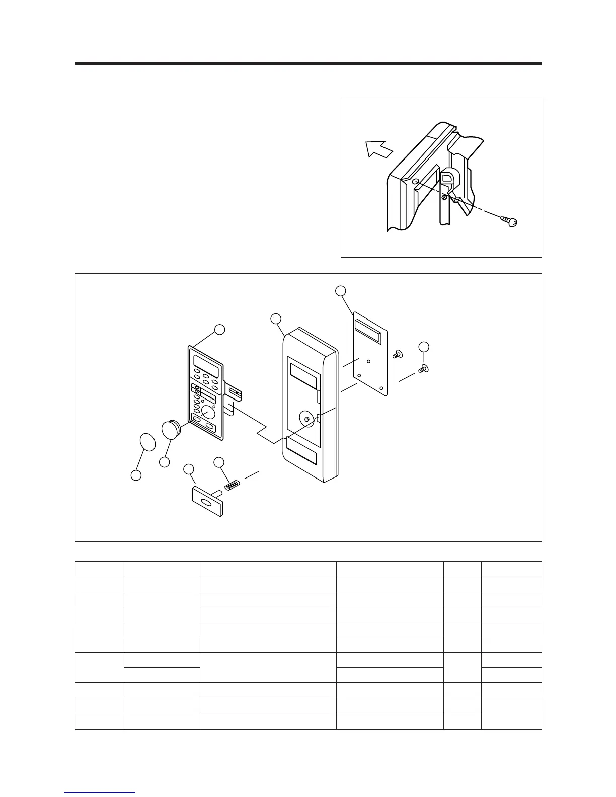
7. To remove control panel assembly. (Refer to Fig. 7, 8)
(1) Remove a screws holding control panel assembly to the
oven front plate.
At the same time, draw forward the control panel assembly
from oven front plate.
(2) Remove two screws ¤ which secure the PCB main
assembly ¤º to control panel ¤ .
(3) Disconnect membrane tail from the connector of the PCB
main assembly.
(4) Detach membrane ¤Œ from the control panel.
REF NO. PART CODE PART NAME DESCRIPTION Q’TY REMARK
B01 3516706700 CONTROL-PANEL P.C 1
B02 441B655072 SPRING DOOR BUTTON HSWR 1
B03 3516902600 BUTTON DOOR OPEN P.C 1
B04
3518505740
SWITCH MEMBRANE
KOC-960P0S
1
3518505940 KOC-960PBS ROTISSERIE
B05
PKMPMSQH00
PCB MAIN AS
KOC-960P0S
1
PKMPMSQJ00 KOC-960PBS ROTISSERIE
B06 7181401211 SCREW TAPPING T2S PAN 4X12 MFZN 2
B07 3514600100 RING KNOB SIR-C607 1
B08 3513401500 KNOB HR-420 1
Fig. 7
Fig. 8
✔ Caution:
In this Service Manual, some parts can be changed for improving, their performance without notice in the parts list. So, if you need the
latest parts information, please refer to PPL(Parts Price List) in Service information Center(http://svc.dwe.co.kr)