This document is a service manual for the Daewoo Microwave Oven, specifically models KOG-8A1R5S, KOG-8A1R5S35, and KOG-8A1R5P. It provides comprehensive information for servicing and maintaining these microwave ovens, including specifications, external views, feature diagrams, control panel descriptions, installation guidelines, operational functions, disassembly and assembly instructions, troubleshooting, measurement and test procedures, wiring diagrams, printed circuit board details, and an exploded view with parts list.
Function Description
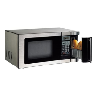
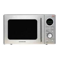
The Daewoo Microwave Oven is designed for cooking, reheating, and defrosting food using microwave energy, and also features grill and combination cooking functions. The oven operates by generating microwave energy that heats food quickly and efficiently. The grill function allows for browning and crisping, while the combination mode integrates both microwave and grill heating for versatile cooking. The control panel offers various cooking programs, power levels, and a timer function for precise operation.
Important Technical Specifications
The microwave oven models KOG-8A1R5S and KOG-8A1R5S35 operate on a 230V, 50Hz single phase with earthing, while the KOG-8A1R5P operates on a 220V, 60Hz single phase with earthing.
- Power Supply:
- KOG-8A1R5S, KOG-8A1R5S35: 230V, 50Hz SINGLE PHASE WITH EARTHING
- KOG-8A1R5P: 220V, 60Hz SINGLE PHASE WITH EARTHING
- Power Consumption:
- Microwave: 1200 W
- Grill: 1050 W
- Combination: 2200 W
- Microwave Energy Output: 800 W
- Microwave Frequency: 2450MHz
- Outside Dimensions (W x H x D): 465 x 287 x 352mm
- Cavity Dimensions (W x H x D): 298 x 230 x 330mm
- Cavity Volume: 23 L
- Net Weight: Approx. 12.7Kg
- Timer: 60 min.
- Power Selections: 10 LEVELS
Usage Features
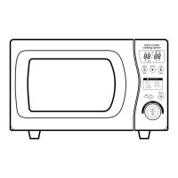
The microwave oven is designed for user-friendly operation with a range of features:
- Display: Shows cooking time, power level, and current program.
- AUTO COOK: Used for cooking with pre-set programs.
- AUTO DEFROST: Defrosts foods by weight.
- Chilled meal: Reheats chilled meals.
- Micro power: Sets the power level for microwave cooking.
- Frozen meal: Reheats frozen meals.
- Grill / Combi: Used for grill or combination cooking.
- Quick defrost: Defrosts food quickly.
- Clock: Sets the clock.
- Dial knob: Used to set time and weight.
- START / Express cook: Starts the oven operation and increases the reheat time by 30 seconds.
- STOP / Clear: Stops the oven operation or clears all entries.
For safe operation, the oven should be placed on a steady, flat surface, with adequate space behind and on the sides for ventilation. It is crucial to ensure the power supply cord is properly connected to an earthed outlet.
Maintenance Features
The manual emphasizes safety precautions for servicing, particularly regarding exposure to microwave energy. Only qualified service personnel should perform repairs.
Safety and Precautions:
- Always disconnect power before servicing.
- Inspect the oven for damage that could cause microwave energy leakage, such as a broken door, damaged door viewing screen, or broken door lock.
- Verify that the microwave emission check is performed after any service involving microwave components.
- The oven is designed for countertop use only.
Disassembly and Assembly:
The manual provides detailed steps for disassembling and assembling various components, including:
- Cabinet removal: Involves removing screws from the cabinet back and pulling the cabinet backward.
- Door assembly removal: Requires removing screws securing the stopper hinge and the door assembly from the top plate of the cavity. Proper alignment of the hinge and cavity front plate is crucial during reassembly.
- Door parts removal: Detailed diagram and parts list for individual door components like the decorator ring, barrier screen, stopper hinge, and hook.
- Gap adjustment: Method to reduce the gap between the door seal and the oven front surface to ensure proper sealing and prevent microwave leakage.
- Control panel removal: Steps to remove the control panel assembly, including screws and connectors.
- High voltage capacitor removal: Instructions for safely removing the capacitor and grounding the ring terminal of the H.V. diode.
- Magnetron removal: Steps to remove the magnetron, with a critical note about checking microwave leakage after replacement.
- Wind guide assembly removal: Instructions for removing the wind guide, fan motor, and motor shaded pole.
- H.V. transformer removal: Steps for removing the high voltage transformer.
- Tray motor removal: Instructions for removing the coupler, tray motor, and tray motor cover.
- Heater assembly removal: Steps for removing the nuts and insulator heater.
Troubleshooting Guide:
Flowcharts are provided to diagnose common issues based on symptoms:
- Fuse blows: Checks continuity of interlock monitor switch, primary and secondary interlock switches, primary winding of low voltage transformer, and high voltage fuse.
- Oven does not start cooking: Checks continuity of magnetron, noise filter board, power supply cord, primary interlock switch, secondary interlock switch, and D.C. voltage to RELAY (RY2) coil.
- No microwave oscillation: Checks continuity of high voltage fuse, high voltage capacitor terminals, high voltage rectifier, magnetron, primary and secondary coil of high voltage transformer, filament terminal of high voltage transformer, and D.C. voltage to RELAY (RY1) coil.
- Defective touch control circuit assembly: Identifies issues like incomplete or missing segments on the display, flickering display, or "0" not displaying when power is on.
Measurement and Test:
- Microwave power output measurement: Procedure to measure the temperature rise of a certain amount of water exposed to microwave energy, allowing calculation of power output.
- Microwave radiation test: Procedure to measure microwave leakage using a microwave energy survey meter, ensuring it does not exceed 4mW/cm².
- Component test procedure: Checks continuity and resistance for high voltage transformer, high voltage capacitor, high voltage diode, magnetron, and fuse.
Wiring Diagram and Printed Circuit Board:
Detailed wiring diagrams for different models (KOG-8A1R5S, KOG-8A1R5S35, KOG-8A1R5P) and a circuit check procedure for the printed circuit board are included, along with wave forms and remedies for common issues. An exploded view with a comprehensive parts list helps identify and order replacement components.