Introduction 2
Inputs 12V DC or 24V AC power. Please be sure to supply
power as instructed in the Guide.
Device abnormity or damage could occur if power is not
supplied correctly.
Outputs analog video signal.
Connecting Alarm Input/output 1.2
Alarm input/output is available on select models.
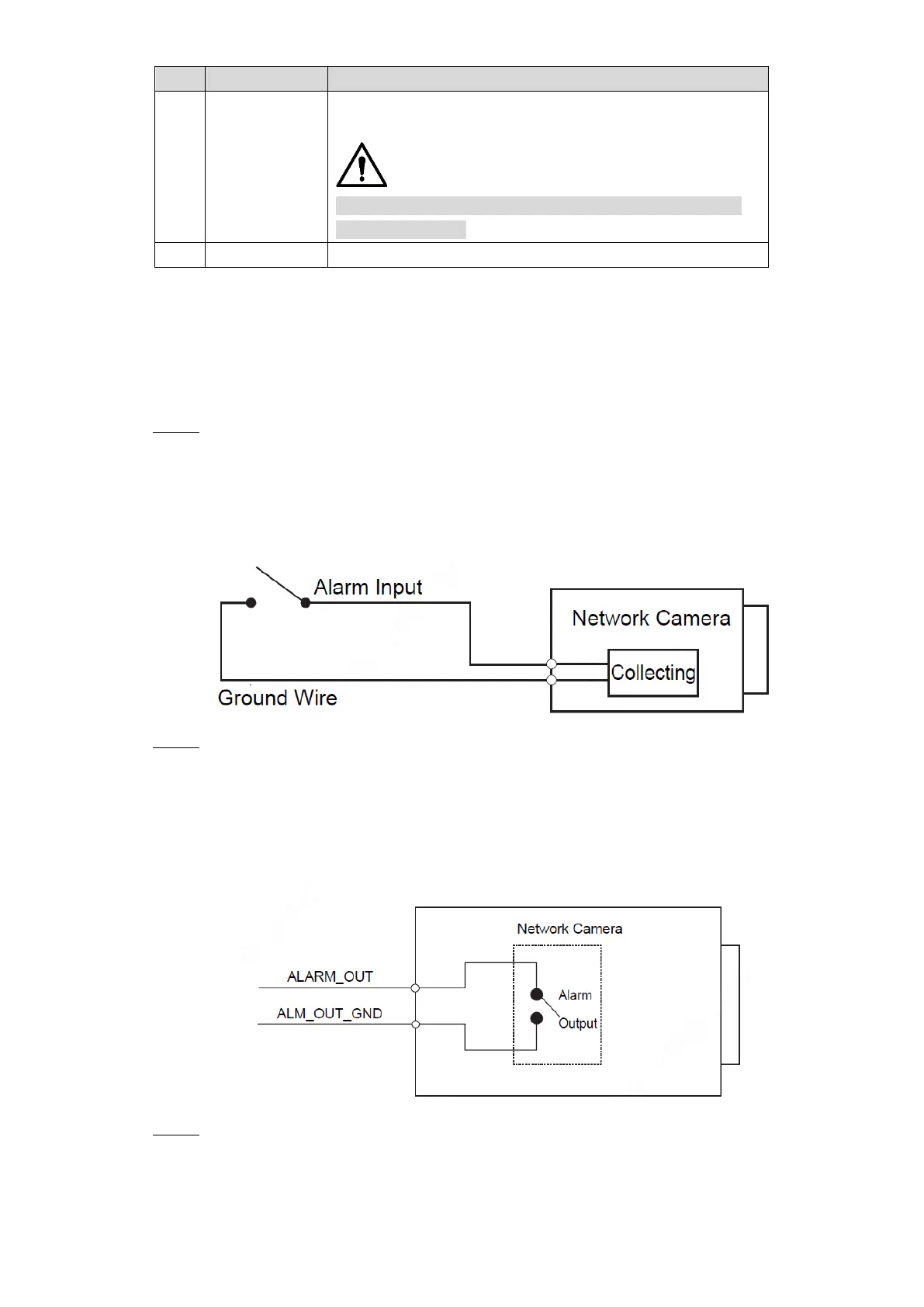
Connect alarm input device to the alarm input end of the I/O port. Step 1
Device collects different states of alarm input port when the input signal is idling and
being connected to the ground.
Device collects logic "1" when input signal is connecting to +3V to +5V or idling.
Device collects logic "0" when input signal being connected to the ground.
Alarm input Figure 1-2
Connect alarm output device to the alarm output end of the I/O port. The alarm output Step 2
is relay switch output, which can only connect to NO alarm devices.
The ALARM_OUT port and the ALARM_OUT_GND port with the same number
constitute a switch for alarm output. See Figure 1-3. The switch is open normally and
closes when there is alarm output.
Alarm output Figure 1-3
Log in web interface, and configure alarm input and alarm output in alarm setting. Step 3
The alarm input in the web interface is corresponding to the alarm input end of the
I/O port. There will be high level and low level alarm signal generated by the alarm
input device when alarm occurs, set the input mode to "NO" (default) if the alarm
 Loading...