User’s Manual
2
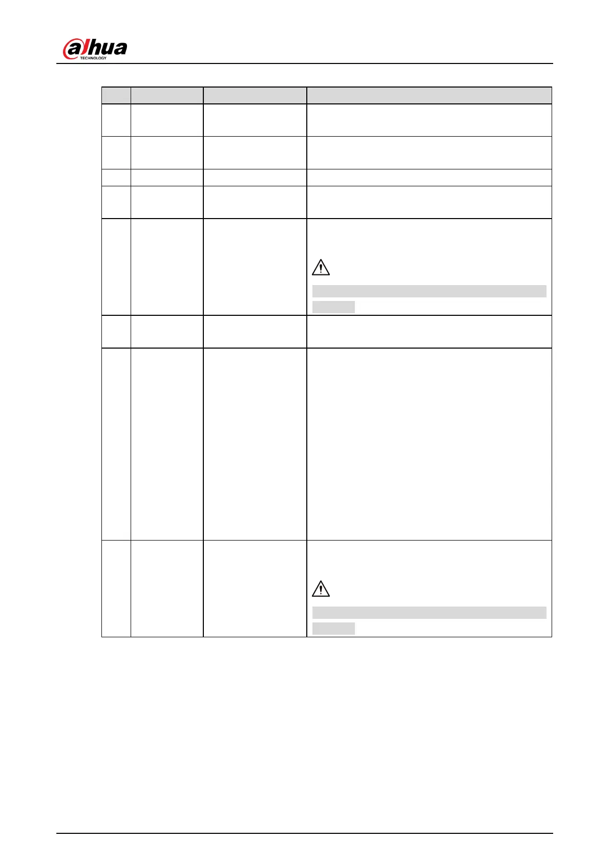
Table 2-3 Cable connection description
1 LAN Ethernet port
Connects to standard Ethernet, supports PoE
power supply.
2 AUDIO OUT Audio output port
The Camera sends out audio signal through this
port.
3 AUDIO IN Audio input port The Camera gets audio signal through this port.
4 BNC Video output port
The Camera sends out video signal through this
port.
5 DC 12V Power inputport
Inputs 12V DC power. Please be sure to supply
power as instructed.
Device damage will occur if power is not supplied
6 RS-485 RS-485 port
Yellow: RS-485_A1
7 ALARM Alarm port
Alarm output, connecting to barrier, and alarm
output devices such as alarm light.
Brown: ALARM_OUT1
Green: ALARM_OUT_GND1
Red: ALARM_OUT2
Black: ALARM_OUT_GND2
Alarm input, connecting to vehicle detector, IR
detector, induction coil, and more.
Blue: ALARM_IN1
White: ALARM_IN2
Yellow: ALARM_IN3
8 AC 24V Power input port
Inputs 24V AC power. Please be sure to supply
power as instructed.
Device damage will occur if power is not supplied
 Loading...