Structure 7
Yellow and green: Ground line
Light green: alarm input 4
Yellow and black: alarm input 7
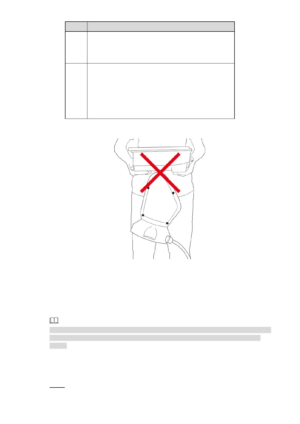
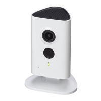
Do not carry the Camera as displayed in Figure 2-7.
Wrong way of carrying the Camera
Figure 2-7
Cable Connection
Connect the multi-functional cable of the bracket to the multi-functional cable (including power
cord, video cable, audio cable, RS-485 control cable, alarm cable, network cable,
high-frequency signal cable, and optical fiber cable) of the Camera. Wrap the cable joints
around with insulated rubber tape and do waterproof operations.
The cable diameter of the RS-485 control cable can not be too large; otherwise the the control
performance can be influenced. For details of the RS-485 cable, see “Appendix 2 RS-485
Cable”.
Alarm Cable Connection
Procedures of alarm cable connection are as follows.
Connect the alarm input device to ALARM_IN and ALARM_GND of the user cable. Step 1