Do you have a question about the Daikin 2MKS40G2V1B and is the answer not in the manual?
Provides essential safety precautions for users and workers.
Explains the meaning of various icons used in the manual.
Details the functions of the air conditioning system.
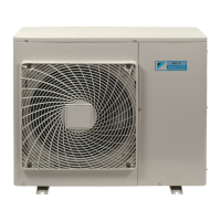
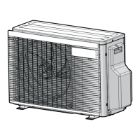
Lists technical specifications for indoor and outdoor units.
Provides wiring diagrams for indoor unit components.
Details the functions of RA model indoor units.
Details the functions of SA model indoor units.
Explains the role and function of thermistors in the system.
Outlines the system's control specifications and logic.
Provides steps for disassembling the outdoor unit.
Details the procedure for pump down operation.
Explains how to perform forced cooling operation.
Guides on performing trial operation for system verification.
Covers various field settings for system configuration.
Details applying silicon grease for heat dissipation.
Visual representation of refrigerant piping connections.
Visual representation of electrical wiring connections.
Guides troubleshooting using LED indicators.
Lists common problems and their solutions.
Details diagnostic functions for service checks.
Explains error codes displayed on the remote controller.
Troubleshooting specific to RA indoor units.
Troubleshooting specific to SA indoor units.
Troubleshooting procedures for the outdoor unit.
Describes various checks and tests for components.
| Model | 2MKS40G2V1B |
|---|---|
| Cooling Capacity | 4.0 kW |
| Heating Capacity | 4.5 kW |
| Refrigerant | R32 |
| Sound Power Level Heating | 62 dBA |
| Outdoor Unit Noise Level | 48 dBA |
| Outdoor Unit Dimensions (WxHxD) | 765x550x285 mm |
| Indoor Unit Weight | 9 kg |
| Outdoor Unit Weight | 34 kg |
| Type | Multi-Split |
| Power Supply | 220-240 V / 50 Hz / 1 Phase |