Do you have a question about the Daikin 2MXM40M and is the answer not in the manual?
Essential safety guidelines, including warnings, cautions, and symbol meanings.
Methods for checking and understanding error codes displayed by the unit.
How to view and reset error codes using the remote control.
Procedures for retrieving and resetting error codes via the outdoor unit's PCB.
Detailed guide for diagnosing and resolving issues based on specific error codes.
Troubleshooting steps for indoor unit error codes.
Troubleshooting steps for outdoor unit error codes.
Troubleshooting procedures for system-wide errors.
Guidance for diagnosing issues that do not trigger specific error codes.
Procedures for checking the functionality of individual unit components.
Component checks specific to the indoor unit.
Component checks specific to the outdoor unit.
Procedure for checking the 4-way valve for proper operation.
Detailed checks for the compressor's electrical and mechanical condition.
Steps for inspecting and testing the electronic expansion valve.
Procedures for checking the fan motor's electrical and mechanical integrity.
Procedures for checking refrigerant thermistors and their resistance values.
Guidelines and procedures for handling refrigerant during repairs.
Safe practices for handling refrigerant piping and connections.
Steps for recovering refrigerant safely from the system.
Method for collecting refrigerant within the outdoor unit for relocation.
Steps for repairing refrigerant piping, including flare making and brazing.
Detailed repair procedures for specific unit components.
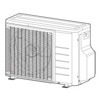
Repair procedures specific to outdoor units.
Steps for replacing the 4-way valve body.
Detailed steps for replacing the compressor unit.
Procedure for replacing the electronic expansion valve body.
Guide for replacing the main printed circuit board (PCB).
Electrical wiring diagrams for various unit models.
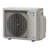
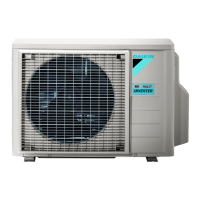
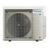
Wiring diagrams for outdoor units.
Piping diagrams illustrating refrigerant flow for various models.
Piping diagrams for outdoor units.
Detailed explanations and conditions for specific error codes.
| Type | Multi Split |
|---|---|
| Cooling Capacity (kW) | 4.0 |
| Cooling Capacity (Btu/h) | 13600 |
| Heating Capacity (kW) | 5.0 |
| Refrigerant | R-32 |
| Maximum Number of Connectable Indoor Units | 2 |
| Seasonal Energy Efficiency Ratio (SEER) | 6.1 |
| Power Supply | 220-240V, 50Hz |