DAMA-SM-21-003 Actuator Check
Service Diagnosis 85
5. Actuator Check
5.1 Thermistor Resistance Check
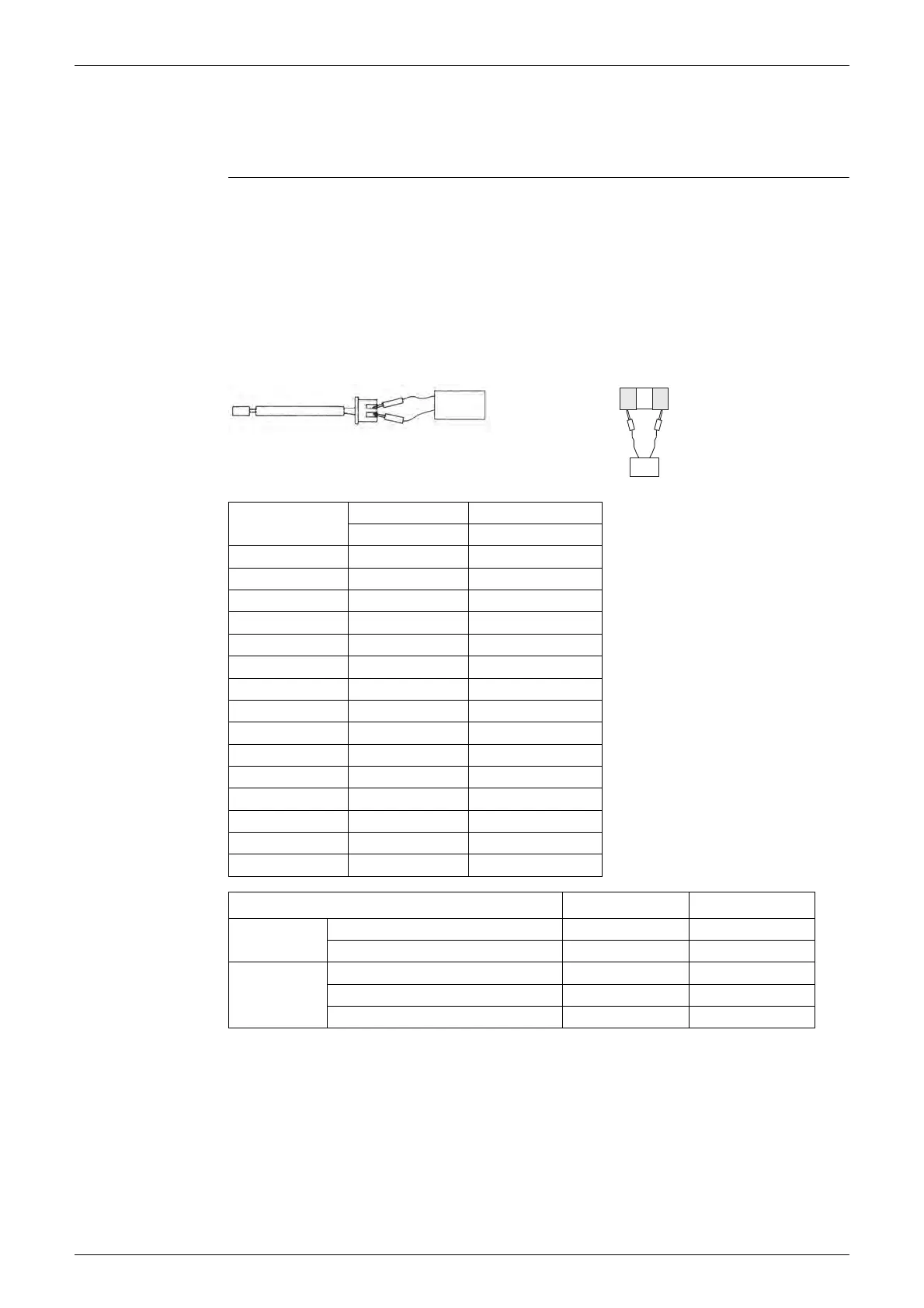
Check No.01 Measure the resistance of each thermistor using multimeter.
The resistance values are defined by below table.
If the measured resistance value does not match the listed value, the thermistor must be
replaced.
Disconnect the connector of t
hermistor ASSY from the PCB to measure the resistance
between the pins using multimeter.
To check the thermistor soldered on a PCB, disconnect the PCB from other PCB/parts, and
measure the resistance between the both ends of soldered thermistor.
Tolerance resistance type A : ±5%
Tolerance resistance type B : ±2%
Multimeter
Resistance range
Thermistor ASSY Soldered thermistor
Multimeter
Thermistor
temperature (°C)
Type A Type B
R(25°C) = 20 k
Ω R(25°C) = 10 kΩ
-20 198 73
-15 149 57
-10 113 45
-5 86 35
066 28
551 23
10 40 18
15 32 15
20 25 12
25 20 10
30 16 8
35 13 7
40 11 6
45 9 5
50 7 4
Thermistor Resistance Type R (25°C) or (77°F)
Indoor Unit
Room temperature thermistor B 10 kΩ
Indoor heat exchanger thermistor B 10 kΩ
Outdoor Unit
Outdoor temperature thermistor A 20 kΩ
Outdoor heat exchanger thermistor A 20 kΩ
Discharge pipe thermistor A 20 kΩ
DAMA-SM-21-003 -Inverter Multi Split-CTX Series.book Page 85 Wednesday, September 1, 2021 5:44 PM
 Loading...