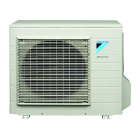
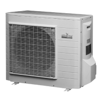
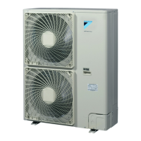
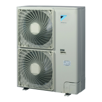
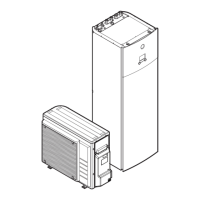
ERHQ006~008ADV3(8)
Outdoor unit for air to water heat pump
4PW49002-1A
Installation manual
3
■ In heavy snowfall areas it is very important to select an
installation site where the snow will not affect the unit. If lateral
snowfall is possible, make sure that the heat exchanger coil is
not affected by the snow (if necessary construct a lateral
canopy).
Refrigerant piping specifications
Installing near a wall or obstacle
■ Where a wall or other obstacle is in the path of the outdoor unit
air intake or exhaust airflow, follow the installation guidelines
below.
■ For any of the installation patterns below, the wall height on the
exhaust side should be 1200 mm or less.
Wall facing one side (unit: mm)
Walls facing two sides (unit: mm)
Walls facing three sides (unit: mm)
Outdoor unit installation drawing
Construct a large canopy.
Construct a pedestal.
Install the unit high enough off the ground
to prevent burying in snow.
Refrigerant piping specifications
Maximum allowable piping length
between outdoor unit and indoor unit
30 m
Minimum required piping length
between outdoor unit and indoor unit
3 m
Maximum allowable height difference
between outdoor unit and indoor unit
20 m
Additional refrigerant required for
refrigerant pipe exceeding 10 m in
length
20 g/m
Gas pipe - outer diameter 15.9 mm (5/8")
Liquid pipe - outer diameter 6.4 mm (1/4")
>100 >350
≤1200
>50
>50
>350
>100
>100
>350
>50
1 Wrap the insulation pipe with finishing tape from bottom to top.
2 Service cover
3 Stop valve cover
4 250 mm from wall. Allow space for piping and electrical servicing.
5 If there is danger of the unit falling or overturning, fix the unit with
foundation bolts, or with wire or other means.
6 Distance from the outer side of the stop valve cover
7 If the location does not have good drainage, place the unit on
block bases. Adjust foot height until the unit is levelled. Failure to
do so may result in water leakage or accumulation.
330 m
m
580 mm
120 mm
4
1
3
2
7
56
 Loading...