EasyManua.ls Logo

Daikin AWST18SU14 AA Series - User Manual

Daikin AWST18SU14 AA Series
16 pages
Print Icon
To Next Page IconTo Next Page
Loading...
IO-4005
08/2022
CONTENTS
1 Important Safety Instructions .............................Pg. 1
2 Shipping Inspection ...........................................Pg. 2
3 Codes & Regulations ..........................................Pg. 2
4 Replacement Parts ..............................................Pg. 2
5 Pre- Installation Instructions .............................. Pg. 2
5.1 Preparation ......................................................Pg. 2
5.2 System Matches ..............................................Pg. 2
5.3 Interconnecting Tubing ....................................Pg. 3
6 Application Information ......................................Pg. 3
6.1 Wire Sizing ......................................................Pg. 3
6.2 Maximum Overcurrent Protection (MOP) ........Pg. 4
6.3 Electrical Connections-Supply Voltage ............Pg. 4
6.4 Fresh Air Openings .........................................Pg. 4
7 AWST-Factory Installed TXV Models ................ Pg. 4
7.1 Tubing Size ..................................................... Pg. 4
7.2 Tubing Connection .......................................... Pg. 4
7.3 Thermal Expansion Valve System Adjustment Pg. 5
8 Maintenance Check ............................................ Pg. 5
9 Wiring Diagrams and Air Flow Data ................... Pg. 6
9.1 Low Voltage Connection .................................Pg. 6
10 Trouble Shooting .............................................. Pg. 11
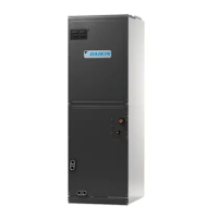
VERTICAL MOUNT AIR HANDLERS

© 2022
19001 Kermier Rd., Waller, TX 77484
www.daikinac.com
P/N: IO-4005 Date: August 2022




SOURCES MAY BE PRESENT. FAILURE TO DO SO

INJURY OR DEATH.


THE EQUIPMENT SPECIFIED IN THIS MANUAL SHOULD
SERVICE THE EQUIPMENT. THE MANUFACTURER WILL
NOT BE RESPONSIBLE FOR ANY INJURY OR PROPERTY


RESPONSIBILITY FOR ANY INJURY OR PROPERTY

JURISDICTIONS THAT REQUIRE ONE OR MORE LICENSES
TO SERVICE THE EQUIPMENT SPECIFIED IN THIS

THE EQUIPMENT.



THE EQUIPMENT SPECIFIED IN THIS MANUAL WITHOUT





-

VAPORS IN THE VICINITY OF THIS APPLIANCE.
CAUTION
HAVE YOUR CONTRACTOR IDENTIFY ALL THE VARIOUS CUT
OFF SWITCHESAND DEVICES THAT SERVICE THIS UNIT.


CAUTION
THIS APPLIANCE IS NOT INTENDED FOR THE USE BY PER-

-


APPLIANCE BY A PERSON RESPONSIBLE FOR THEIR SAFETY.
CHILDREN SHOULD BE SUPERVISED TO ENSURE THAT THEY
DO NOT PLAY WITH THE APPLIANCE.



CERTIFIED FOR USE WITH THIS UNIT OR HAVE NOT BEEN
TESTED AND APPROVED BY THE MANUFACTURER. SERIOUS

PERFORMANCE AND/OR HAZARDOUS CONDITIONS MAY
RESULT FROM THE USE OF DEVICES THAT HAVE NOT BEEN
APPROVED OR CERTIFIED BY THE MANUFACTURER.
1 Important Safety Instructions
As a professional installer, you have an obligation to know
the product better than the customer. This includes all safety
precautions and related items. Prior to actual installation,
thoroughly familiarize yourself with this Instruction Manual.
Pay special attention to all safety warnings. Remember, it is
your responsibility to install the product safely and to know it
well enough to be able to instruct a customer in its safe use.
Safety is a matter of common sense...a matter of thinking before
acting. Most dealers have a list of specic, good safety
practices...follow them.
The precautions listed in this Installation Manual are in- tended
as supplemental to existing practices. However, if there is a
direct conict between existing practices and the content
of this manual, the precautions listed here take precedence.
Question and Answer IconNeed help?

Do you have a question about the Daikin AWST18SU14 AA Series and is the answer not in the manual?

Summary

Important Safety Instructions

General Safety Precautions

Critical safety warnings including high voltage, proper use, service personnel, and materials.

Codes & Regulations

Pre-Installation Instructions

Application Information

Electrical Connections - Supply Voltage

Details on connecting supply voltage, including grounding and voltage verification.

AWST-Factory Installed TXV Models

Thermal Expansion Valve System Adjustment

Procedure for adjusting the TXV to achieve correct subcooling and superheat.

Maintenance Check

Wiring Diagrams and Air Flow Data

Low Voltage Connections

Details on making low voltage connections to the thermostat and condenser.

Trouble Shooting

Overview

This document outlines the installation, operation, and maintenance of Vertical Mount Air Handlers, emphasizing safety, proper setup, and troubleshooting for optimal performance.

Function Description:

Vertical Mount Air Handlers are designed to be integrated into a complete HVAC system, working in conjunction with an outdoor condenser or heat pump to provide heating and cooling for indoor spaces. These units are specifically designed for vertical "upflow" installations, either recessed into a wall or hung. They are equipped with a blower to circulate air, an evaporator coil for heat exchange, and connections for refrigerant lines and electrical supply. Many models include factory-installed, fully adjustable Thermal Expansion Valves (TXVs) to regulate refrigerant flow and ensure efficient operation. The units are designed to accommodate fresh air intake through knockouts on the cabinet sides, allowing for improved indoor air quality. They also feature both primary and secondary condensate drains to manage moisture removal, preventing water damage. The air handlers are designed to operate within specific altitude ranges, from 10,500 feet above sea level to 184 feet below sea level.

Usage Features:

The air handlers are designed for flexible installation, supporting both bottom and front return air configurations. For recessed wall installations, the unit can be attached to framing studs using holes along the inside of the front flange. For hanging applications, an offset hanging bracket is provided at the rear of the cabinet. Proper leveling or a slight backward tilt is crucial during installation to ensure effective condensate drainage. The units are shipped with a filter rack and filter, which are essential for maintaining indoor air quality and protecting internal components. Regular inspection, cleaning, and replacement of the filter are recommended monthly.

Electrical connections are made through a knockout on the top or side panel of the air handler, requiring copper conductors and an NEC or CEC approved strain relief. The unit is designed for single-phase electrical supply, and it is critical to ensure that the supply voltage matches the unit's nameplate requirements. Low voltage connections are made to the room thermostat and outdoor unit, with various wiring schemes possible depending on the presence and type of heat kit (single-stage or multi-stage) and outdoor section (air conditioner or heat pump, single-stage or two-stage). The manual provides detailed wiring diagrams and blower charts to guide installers in selecting appropriate fan speeds and ensuring correct electrical hookups.

For models with factory-installed TXVs, the system requires specific adjustments to achieve optimal superheat and subcooling values. This involves running the system in cooling mode for 15 minutes to stabilize refrigerant pressures, connecting service gauges, and using a thermometer to measure liquid and vapor temperatures. Adjustments to the TXV valve stem are made clockwise to increase superheat and counterclockwise to decrease it, with a target range of 7 to 9°F for both superheat and subcooling. The unit is factory-shipped with R410A refrigerant and dry nitrogen mixture gas under pressure, necessitating appropriate service tools and safety procedures during installation and maintenance.

Maintenance Features:

Routine maintenance is crucial for the long-term reliability and efficiency of the air handler. The manufacturer strongly recommends biannual checkups by a qualified servicer before the heating and cooling seasons. Key maintenance tasks include:

  • Filter Replacement/Cleaning: The most critical user-level maintenance is regularly checking and replacing or cleaning the air filter. Operating the unit without a filter can lead to dust and lint buildup on internal parts, reducing efficiency, damaging equipment, and posing a fire risk. Disposable filters should be replaced, while reusable filters can be cleaned.
  • Coil Cleaning: The aluminum tube evaporator coil should be cleaned periodically. The safest method is to flush the coil with water. Alternatively, approved cleaning products listed in the technical publication TP-109 can be used by a qualified servicer. It is essential to rinse the coils thoroughly after using chemical cleaners.
  • Condensate Drain Maintenance: Both primary and secondary drains must be trapped, unless an emergency condensate switch is installed in the secondary drain. Failure to install a trap can cause condensate to overflow and result in water damage. Insulating the condensate drain line inside the building may be necessary to prevent sweating and dripping.
  • Electrical System Checks: Before servicing, all power to the unit must be disconnected to prevent electrical shock. This includes identifying and cutting off all power sources. The manual provides warnings about high voltage and the importance of proper grounding.
  • Troubleshooting TXV Systems: The manual includes a dedicated section for troubleshooting expansion valve issues, such as "starving" (low suction pressure, insufficient cooling) or "flooding" (compressor frosting, moisture condensing at suction connection). This involves checking superheat, adjusting the TXV, and potentially reclaiming refrigerant to inspect for dirt, debris, or loss of Power Element charge.
  • General Checks: Users are advised to check the thermostat settings, wait 15 minutes for automatic resets of protective devices, inspect electrical panels for tripped circuit breakers or failed fuses, and ensure the disconnect switch near the indoor unit is closed. Obstructions around the outdoor unit and blockages of indoor air inlets/outlets should be removed. Any unusual noises from the unit should prompt a call to a qualified servicer.

The unit's design prioritizes reduced air leakage, with gaskets ensuring that cabinet air leakage remains below 2% at 1.0 inch H2O and below 1.4% at 0.5 inch H2O, as tested in accordance with ASHRAE Standard 193. This contributes to overall system efficiency and performance.

Daikin AWST18SU14 AA Series Specifications

General IconGeneral
ModelAWST18SU14
TypeAir Handler
Cooling Capacity (Ton)1.5 Ton
SeriesAA Series
RefrigerantR-410A
Voltage208/230V
Phase1
Frequency60 Hz
Cooling Capacity18000 BTU/h
Heating Capacity20, 000 BTU/hr
Static Pressure0.5 in. wg

Related product manuals