5 Installation
Installation manual
6
FNA25~60A2VEB(9)
Split system air conditioners
4P456958-1J – 2020.12
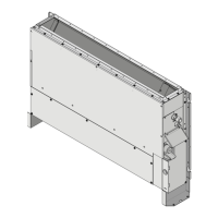
A Securing the hanger bracket
B Securing the washers
a Washer (accessories)
b Hanger bracket
c1 Nut (field supply)
c2 Double nut (field supply)
d Washer fixing plate (accessory)
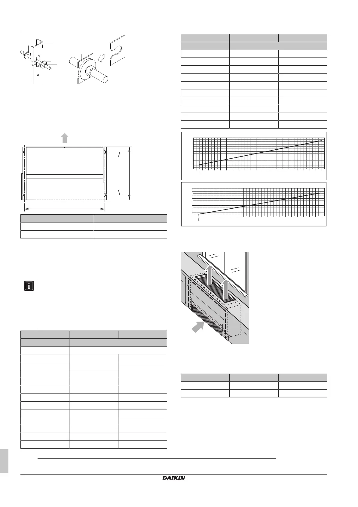
▪ Suspension bolt pitch for fastening to the wall:
Class A(mm)
25&35 740
50&60 1140
Minimum floor area
(1)
To determine the minimum floor area, refer to the table or the graph
below.
1 Depending on the amount of the total refrigerant charge in the
system (m), the minimum floor area is (A
min
).
INFORMATION
▪ If the required exact value for the total refrigerant
charge in the system (m) is not listed below, use the
closest higher value.
▪ In case the total refrigerant charge in the system is
>3.9 kg, refer to "To determine the minimum floor
area" in the General safety precaution.
FNA25&35 FNA50&60
m(kg) A
min
(m
2
)
≤1.842 No requirements
1.843 6.2 5.5
1.9 6.4 5.7
2 6.8 6.0
2.1 7.1 6.3
2.2 7.4 6.6
2.3 7.8 6.9
2.4 8.1 7.2
2.5 8.4 7.5
2.6 8.8 7.8
2.7 9.1 8.1
2.8 9.5 8.4
2.9 9.8 8.7
FNA25&35 FNA50&60
m(kg) A
min
(m
2
)
3 10.1 9.0
3.1 10.5 9.3
3.2 10.8 9.6
3.3 11.1 9.9
3.4 11.5 10.2
3.5 11.8 10.4
3.6 12.2 10.7
3.7 12.5 11.0
3.8 12.8 11.3
3.9 13.2 11.6
5
6
7
8
9
10
11
12
13
14
2 2.11.91.8 2.2 2.3 2.5 2.7 2.9 3.1 3.3 3.52.4 2.6 2.8 3 3.2 3.4 3.6 3.8 3.93.7
m [kg]
A
min
[m
2
]
FNA25&35
5
6
7
8
9
10
11
12
13
1.8
1.843
2 2.11.9 2.2 2.3 2.5 2.7 2.9 3.1 3.3 3.52.4 2.6 2.8 3 3.2 3.4 3.6 3.8 3.93.7
m [kg]
FNA50&60
A
min
[m
2
]
1.843
A
min
Minimum floor area
m Refrigerant charge amount in the system
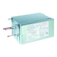
Floor-standing installation
A Maintenance area width
B Air inlet grille width
a Air outlet direction
b Air inlet grille height
c Air inlet direction
Class A(mm) B(mm)
25&35 1350 660
50&60 1750 1060
(1)
Only for units using R32 refrigerant in combination with a user interface BRC1H52*. Refer to the outdoor unit specifications for the type of
refrigerant to be used.