5 Installation
Installation manual
7
FNA25~60A2VEB(9)
Split system air conditioners
4P456958-1J – 2020.12
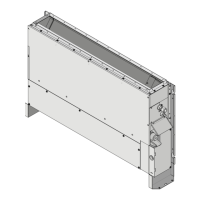
Wall-mounted installation
A Maintenance area width
B Air inlet grille width
a Air outlet direction
b Air inlet grille height
c Air inlet direction
Class A(mm) B(mm)
25&35 1350 660
50&60 1750 1060
▪ External static pressure. Refer to technical documentation to
ensure that the unit's external static pressure is not exceeded.
▪ Removing the legs. If it is necessary to remove the legs, follow
these instructions:
A Bottom view
B Side view
a Protective grille
b Leg
1 In case of bottom suction, remove the air filter.
2 Remove 4 screws (2 on each side) that hold both legs on the
bottom side of the unit.
3 Remove 2 screws (1 on each side) on the side of the unit.
4 In case of bottom suction, reattach the filter.
5 In case of front suction, reinstall 2 screws on the side of the
unit.
▪ Install suction cover and air filter (accessory)
6 In case of front suction, remove the protective grille and the
suction cover from the front side.
A Removing the suction cover
B Reattaching the suction cover
a Suction cover
b Protective grille
c Air inlet
d Air outlet
7 Remove one leg on the opposite side of the electronic
component box.
8 Reattach the removed suction cover to the bottom side.
9 Attach the protective grille to the front side.
10 Reattach the leg if necessary.
11 Attach the air filter (accessory) by pushing down the hooks (2
hooks for 25+35 type, 3 hooks for 50+60 type).
A Front suction
B Bottom suction
a Main unit
b Filter
▪ Install the unit temporarily.
12 Attach the hanger bracket to the suspension bolt.
13 Fix the unit securely.
14 Adjust the unit to fit between the walls.
▪ Level. Make sure the unit is level at all four corners using a level
or a water-filled vinyl tube.
15 Tighten the upper nut.
NOTICE
Do NOT install the unit tilted. Possible consequence: If
the unit is tilted against the direction of the condensate flow
(the drain piping side is raised), the float switch might
malfunction and cause water to drip.
▪ Fixing the unit. Level the unit with the levelling screws
(accessory). If the floor is too uneven to level the unit, place the
unit on a flat and levelled base. If the unit is in danger of falling
over, fasten it to the wall using factory-made holes or to the floor
using floor fasteners (field supply).