11
Note 3.
You have a choice of 5 temperature sensors.
1.) Indoor Sens – Temperature sensor located in the
indoor unit.
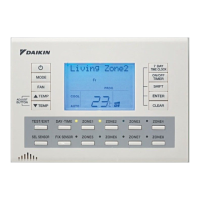
2.) Master RC - Master controller sensor
3.) Sub RC - When using option BRCSZC Sub controller.
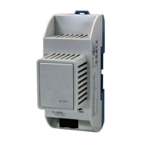
4.) Sens 1 - When using option KRCSO1-1
5.) Sens 2 - When using option KRCSO1-1
Only the indoor sensor will be activated
(factory set) all other sensors must be activated by
the field set codes, once activated sensor selection
can be achieved by pressing the SEL SENSOR
button on the remote controller.
Temperature sensor activation
Zone restriction
Note 4.
Example: You may only require the use of 4 zones out
of the 8 available zones. By applying the Field setting
1b - 3 - 0_ you can restrict the number of zones you
want to operate, for example 4 zones. The remaining
unused zones will not function when the zone buttons
are pressed. ( 1b - 3 - 04 )
Before setting zone restriction make sure all zones are
switched off.
001
Sensor 1 OFF
101
Sensor 2 OFF
002
Sensor 1 ON
(Remote sensor KRCSO1-1 required)
102
Sensor 2 ON
(Remote sensor KRCSO1-1 required)
301
Zone 1 only
302
Zones 1-2
303
Zones 1-3
304
Zones 1-4
305
Zones 1-5
306
Zones 1-6
307
Zones 1-7
308
Zones 1-8
401
Keep 1 Zone ON
402
All Zones OFF
501
Master RC OFF
502
Master RC ON
601
Sub RC OFF
602
Sub RC ON
(Sub controller BRCZSC required)
601
Standard static pressure
(FDYQ(N)71-160 only)
602
High static pressure
(FDYQ(N)71-160 only)
301
Filter sign indication ON
302
Filter sign indication OFF
Set item
1b
Field Settings
Mode Switch Position
23
20
001
Sensor 1 OFF
101
Sensor 2 OFF
308
8 Zones available
402
All zones OFF
501
Master RC OFF
601
Sub RC OFF
201
Fan operation heating (Thermo off.)
701
Fan operation cooling (Thermo off.)
23 601
Standard static pressure
(FDYQ(N)71-160 only)
20 301
Filter sign indication ON
1b
Default Settings Set item
Note 3.
Pg11
Note 4.
Pg11
Note 6.
Pg12
Note 3.
Pg11
Note 5.
Pg11
Fan static Pressure
Note 5.
When a higher airflow is required for example when the
pressure inside the ducting is high, use field setting
23-6-02 to increase the airflow.
For models with a capacity index of 180-250 please
refer to the installation instructions supplied with the air
conditioner.
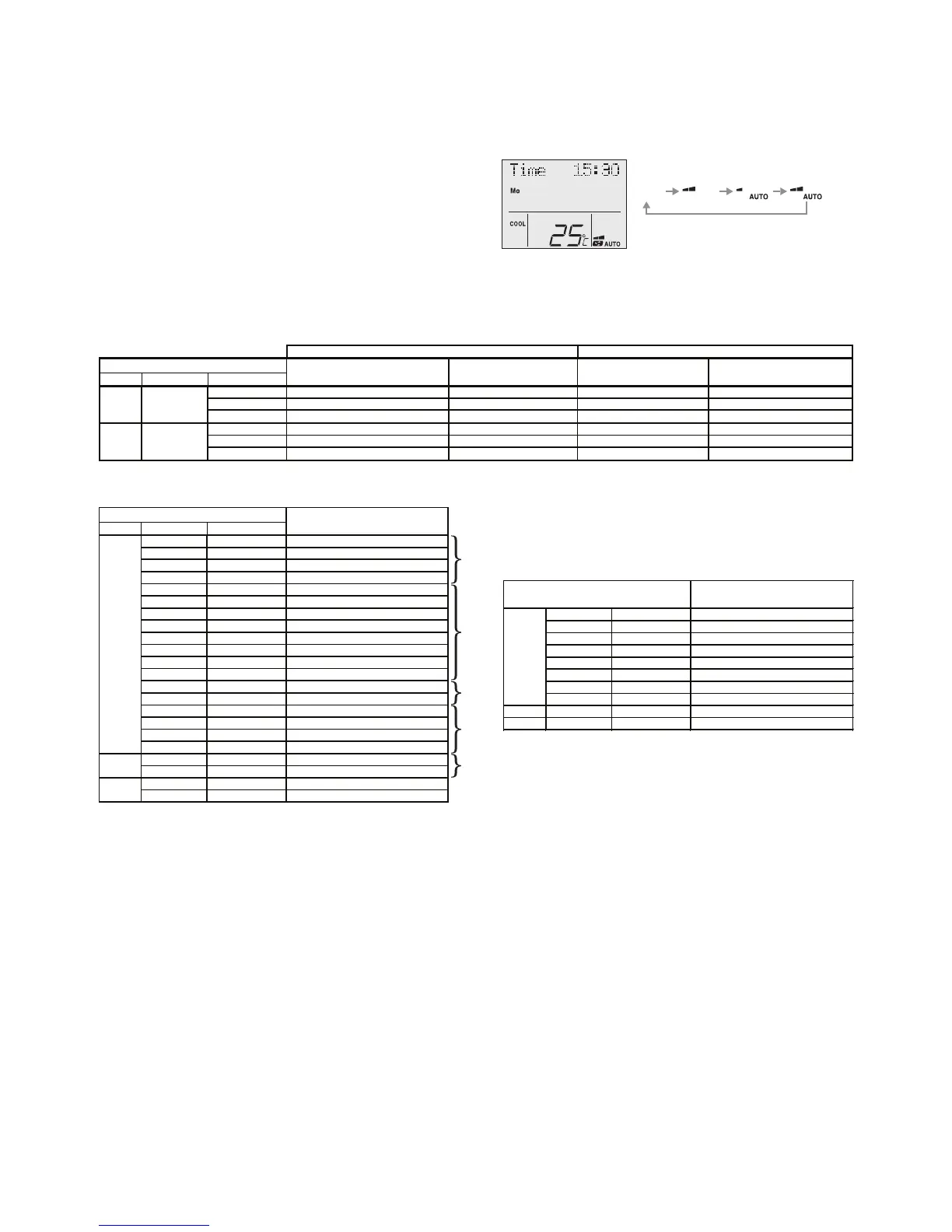
Auto fan function with air sampling mode
Auto fan function will activate once the set point
temperature is achieved (thermo off) and will
deactivate when the room temperature is outside the
set point range (thermo on).
During Auto fan function the indoor fan will stop for a
period of 6 minutes and then start for a period of 30
seconds or more (depending on model) in order to
sample the room temperature.
Auto fan function will only activate when the “Indoor
Sens” (Indoor unit air temperature sensor) is selected.
Auto fan function will operate the same as Std. fan
function when other sensors are selected.
Fan operation during thermo. Off
Mode Switch Position
01
LL OFF (Air sampling LL)LLOFF (Air sampling LL)
02
Set speed OFF (Air sampling Set speed)Set speed OFF (Air sampling Set speed)
03
OFFOFF (Air sampling OFF) OFFOFF (Air sampling OFF)
1
LL OFF (Air sampling LL)Set speed
2
Set speed OFF (Air sampling Set speed)Set speed
3
OFFOFF (Air Sampling OFF)Set speed
Set speed
Set speed
Set speed