9
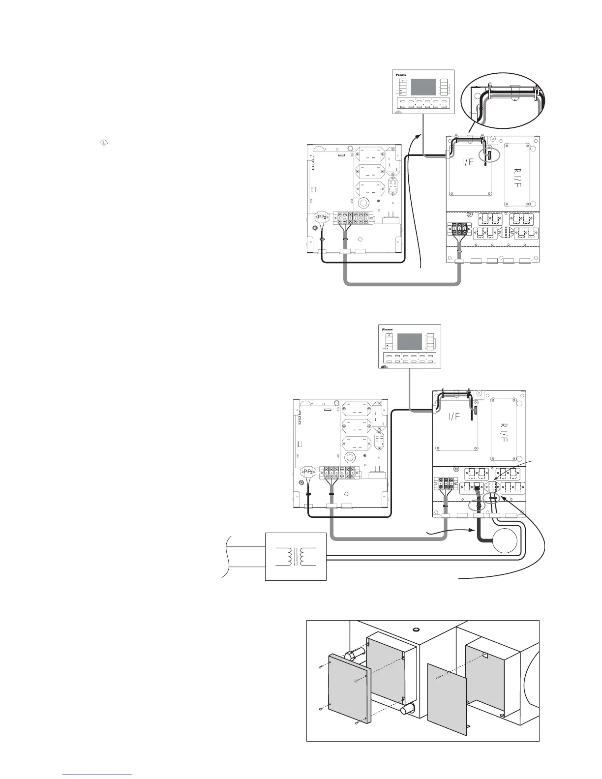
Step 4.
Pass the remote controller cable through the two open
cable ties (factory supplied).
Connect the remote controller cable to the Interface
PCB ( A1P) by inserting the remote controller cable plug
into socket S8. (Fig.4)
Wire the shield wire of the remote controller cable to
the shield fastening point. (Fig.4a)
Note 4:
When installing KRCSO1-1 (option) or BRCSZC
(option), do not tighten the cable ties until you have
passed all cables through the 2 open cable ties.
Tighten the 2 cable ties to anchor. (Fig.4a)
Step 5.
Connect the zone motor RJ12 plugs into the respective
zone sockets. (zone motors and leads field supplied)
By using a cable tie secure zone motor leads to the
anchor as shown in (Fig.5)
Step 6.
Wire 24V AC supply leads from the transformer (field
supplied) to the terminal block X5M located in the
zone controller box. (Fig.5)
By using a cable tie secure the 24V supply cable to
the anchor. (Fig.5)
Important: Ensure the transformer is adequately
sized for the zone motor electrical load and is
suitable for the installation conditions. (FIELD
SUPPLIED)
Note5:
Refer to DSI settings on page12 before installing the
zone controller box cover.
Step 7.
Install the indoor unit electrical box cover and the Zone
control box cover. (Fig.6)
Ensure the cover fits tightly and cables are not in
contact with the underside of cover or cover edges.
24VAC
Remote controller wiring
LNE
LNE
S7
(AIP)
S8
MODE
FAN
TEMP
ADJUST
BUTTON
TEMP
SHIFT
7 DAY
TIME CLOCK
ON/OFF
TIMER
ENTER
CLEAR
TEST/EXIT DAY TIME ZONE1 ZONE2 ZONE3 ZONE4
SEL SENSOR
FIX
SENSOR
ZONE5 ZONE6 ZONE7 ZONE8
Fig.4
Fig.6